
Method for judging targeting of simulated shooting for tank element training based on image analysis

An image analysis and determination method technology, applied in image analysis, image data processing, instruments, etc., can solve the problems of inability to imitate the flight trajectory of shells, large light spots, difficulty in accurately judging whether to hit and distinguish the hit parts, etc., to achieve Conducive to the effect of combat ability and strong scalability

Inactive Publication Date: 2011-07-06
中国人民解放军蚌埠坦克学院 +1
View PDF1 Cites 14 Cited by
  • Summary
  • Abstract
  • Description
  • Claims
  • Application Information

AI Technical Summary

Problems solved by technology

[0004] (2) Laser training "one hit and destroy" is very different from real shells, and it is difficult to accurately judge whether to hit and distinguish the hit part
Because the laser always has a certain divergence angle, as the target distance increases, the laser spot formed by the laser reaching the target is very large, which makes it difficult to accurately judge whether it hits and where it hits, and it is difficult to perform damage assessment, so most of the judgments are made. Destroy and withdraw from the battle; while the size of the real shell is fixed and does not increase with the increase of the flight distance, and the hit part is also a small part
[0005] (3) Laser training "laser travels in a straight line" cannot imitate the flight trajectory of real shells
[0006] With the development of modern military technology and tank equipment, this training method cannot fully meet the needs of military modernization in terms of accuracy and performance.

Method used


Image

  • Method for judging targeting of simulated shooting for tank element training based on image analysis
  • Method for judging targeting of simulated shooting for tank element training based on image analysis
  • Method for judging targeting of simulated shooting for tank element training based on image analysis

Examples


Embodiment Construction

[0022] The present invention is based on the image analysis tank unit training simulated shooting hit determination method, the steps are as follows:

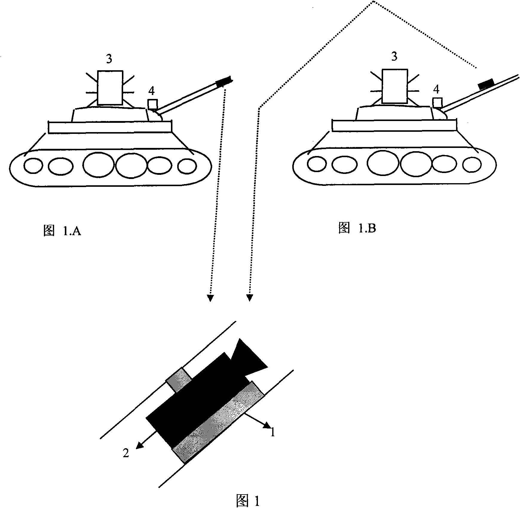
[0023] Step 1: Installation of the camera device. Install a forward-facing camera 2 on the gun barrel of one's own tank, the camera is installed on a dual-axis tilt sensor 1, and the tilt sensor provides the horizontal and pitch angles of the camera; the camera is installed with a filter of a specific wavelength, and can only receive specific wavelengths The light, when specifically implemented, is consistent with the wavelength range of the invisible light source in the present invention, such as an infrared filter with a wavelength of 830-880nm. The camera is used to obtain the image containing the opponent (front) target (tank, armored vehicle, etc.), and the angle sensor is used to obtain the angle between the image row coordinates and the horizontal line caused by the tank's left-right tilt and roll. Note that the horizon...


PUM


Abstract

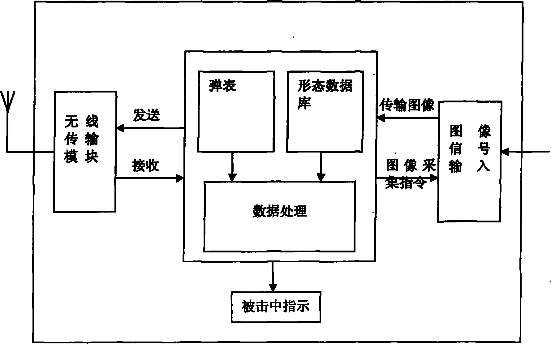
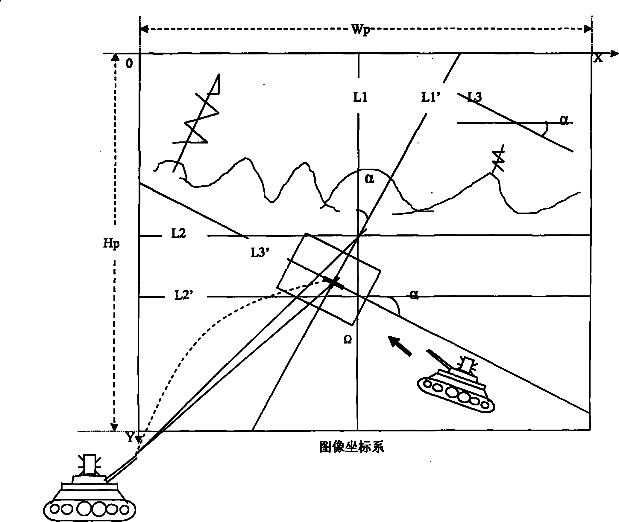
The invention discloses a method for judging the targeting of simulated shooting for tank element training based on image analysis, which comprises the following steps of: installing a video camera facing forwards on one's own gun barrel, and acquiring images by using the video camera, wherein the optical axis of the video camera coincides with or is parallel to the axis of the gun barrel or the axis of a sighting telescope; installing the video camera on a dual-axis tilt sensor in parallel, and providing the horizontal angle and the pitch angle of the video camera by the tilt sensor; installing invisible infrared light sources with different flicker frequencies and beats on different targets to mark the numbers and the indicating positions of the targets; starting to collect images when one's own gunner sights the target, and stopping collection until the gunner presses a shooting button and images that a cannonball reaches the target; and transmitting the collected images to a processing unit, detecting the existence of the light source in each image and the position of the light source by the processing unit, obtaining the flicker frequencies and the beats of the light sources in the visual field through multiple continuous images so as to obtain the identity of a tank, and judging whether the target is hit and the hitting position.

Description

technical field [0001] The invention belongs to the technique of judging whether a tank hits a target by using image analysis, in particular to a method for judging whether a tank hits a target in training simulated shooting based on image analysis. Background technique [0002] At present, tank training mainly uses advanced technologies such as lasers, computers, and wireless communications, and uses lasers instead of live ammunition. This multifunctional integrated laser red-blue confrontation training simulation system (referred to as MILES) [Mao Dexiang, Lin Lifeng. Wireless laser simulation shooting training system [D], Dalian University of Technology, 2006] is mainly composed of a laser transmitter and a detector. When the weapon shoots, the MILES of one's own side emits an infrared laser parallel to the line of sight, and the target person or target vehicle is equipped with an infrared laser detector, and the microprocessor on the detector analyzes the received signal...

Claims


Application Information

Patent Timeline
Patent Type & Authority Applications(China)
IPC IPC(8): F41J1/08G06T7/00
Inventor 邵学海任明武陈璐刘长征顾红
Owner 中国人民解放军蚌埠坦克学院
Learn More