
Physical experimental apparatus box and exploration physical experimental paradigm

A technology of physical experiments and instrument boxes, which is applied in the field of experimental instruments, can solve the problems of a large number of students and the inability to satisfy students to do experiments by themselves, and achieve the effect of easy portability, small size and low cost

Inactive Publication Date: 2011-07-06
胡勇
View PDF3 Cites 7 Cited by
  • Summary
  • Abstract
  • Description
  • Claims
  • Application Information

AI Technical Summary

Problems solved by technology

Doing experiments by yourself can help you understand the concepts of physics and master the laws of physics. However, in the current physics teaching process, due to the small number of laboratories and the large number of students in many schools, they only do some demonstration experiments, which cannot satisfy students to do experiments by themselves. requirements

Method used


Image

  • Physical experimental apparatus box and exploration physical experimental paradigm
  • Physical experimental apparatus box and exploration physical experimental paradigm
  • Physical experimental apparatus box and exploration physical experimental paradigm

Examples


Embodiment 1

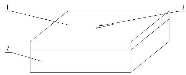
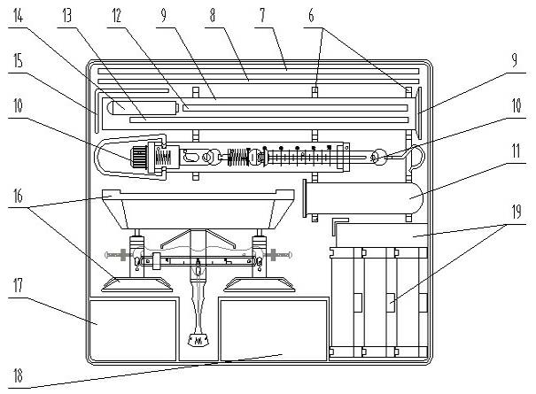
[0034] Example 1 as attached Figure 1-3 Shown: a kind of physical experiment instrument box, box cover 1 is provided with two through holes 3 that cooperate with lever bracket 6 mounting bolts, one side of the back side of box cover 1 is provided with blind hole 4, and the middle part of box cover 1 back side is provided with There are two parallel raised strip guide rails 5; the inner cavity of the box body 2 is provided with a bracket 6, the measuring cylinder 9, the spring dynamometer 10, and the flask 11 are respectively clamped on the bracket 6, and the lever bracket 7, Lever crossbeam 8 and flask support 15, thermometer 12 pulley support 13 and laser pointer 14 are placed in measuring cylinder 9 inner cavity; Small parts grid 18 and optical large parts grid 19; place fixed pulley 20, movable pulley 21 and hook code 23 in optical small parts grid 18, place optical tool socket 24, small hole plate 29, white screen in optical large parts grid 19 30. Convex lens 31, plan...

Embodiment 2

[0035] Example 2 : Understand the structure and use of the tray balance 16, and use tweezers and weights to weigh objects within 19g.

Embodiment 3

[0036] Example 3: Measure the volume of the irregularly shaped object with the measuring cylinder 9: put the small irregularly shaped object into the measuring cylinder 9 filled with half a cylinder of water, observe and record the change of the water level scale.


PUM


Abstract

The invention discloses a physical experimental apparatus box, wherein a box cover is provided with two through holes matched with mounting bolts of a lever support, one side of the reverse side of the box cover is provided with a bind hole, and the middle part of the reverse side of the box cover is provided with two raised-strip guide rails in parallel; the inner cavity of a box body is provided with a bracket which is provided with a measuring cylinder, a spring dynamometer and a flask respectively in clamping way, the lever support, a lever cross beam and a flask support are arranged beside the measuring cylinder, and the inner cavity of the measuring cylinder is provided with a thermometer pulley support and a laser pen; a counter balance is arranged beside the spring dynamometer, and a mechanical part case, an optical small-part case and an optical bid-part case are arranged at two sides of the tip of the counter balance; and the optical small-part case is internally provided with a fixed pulley, a movable pulley and hook weights, and the optical big-part case is internally provided with an optical socket, a small pore plate, a white screen, a convex lens, a plane mirror, plane glass and a circular dial scale. The physical experimental apparatus box disclosed by the invention has the advantages of small size, multiple purposes, portability and low cost, can be taken by every student who participates in a physical experiment, and can meet the requirements for making experiments independently by the students.

Description

technical field [0001] The invention relates to an experimental instrument. In particular, the utility model relates to an experimental instrument box and an example of exploring a physical experiment. Background technique [0002] Physics is an experimental science, which requires students to do a lot of experiments to strengthen their understanding and master the knowledge they have learned. Doing experiments by yourself can help you understand the concepts of physics and master the laws of physics. However, in the current physics teaching process, due to the small number of laboratories and the large number of students in many schools, they only do some demonstration experiments, which cannot satisfy students to do experiments by themselves. requirements. Contents of the invention [0003] The object of the present invention is to provide a small, smart, multi-purpose, portable physical experiment instrument box and a physical experiment paradigm. [0004] The techni...

Claims


Application Information

Patent Timeline
Patent Type & Authority Applications(China)
IPC IPC(8): G09B23/06
Inventor 胡勇
Owner 胡勇
Learn More