DC-DC converter based on coupling inductors

A DC-DC and coupled inductor technology, applied in the field of converters, can solve problems such as reduced reliability of equipment, high voltage stress of switch tubes, and complex design, and achieve the effects of reducing peak voltage stress, increasing boost ratio, and improving efficiency

Inactive Publication Date: 2011-07-06
NORTHEASTERN UNIV
View PDF1 Cites 11 Cited by
  • Summary
  • Abstract
  • Description
  • Claims
  • Application Information

AI Technical Summary

Problems solved by technology

[0003] At present, bidirectional DC-DC converters mostly adopt non-isolated BUCK / BOOST topology. Due to the limitation of topology, the main problem of bidirectional DC-DC converter is that the gain of boost mode is low. In order to improve its gain Voltage ratio, need to change the circuit topology, which will make the circuit topology complex, resulting in reduced reliability of equipment
Although the step-up ratio can be improved by introducing a transformer, the transformer is large in size and complex in design, which is not conducive to the realization of
The boost ratio can also be improved by introducing a coupled inductor, but due to the existence of the leakage inductance of the coupled inductor, the voltage stress of the switch tube is too large, causing new problems

Method used


Image

  • DC-DC converter based on coupling inductors
  • DC-DC converter based on coupling inductors
  • DC-DC converter based on coupling inductors

Examples


Embodiment Construction

[0019] The present invention is described in detail in combination with specific embodiments and accompanying drawings.

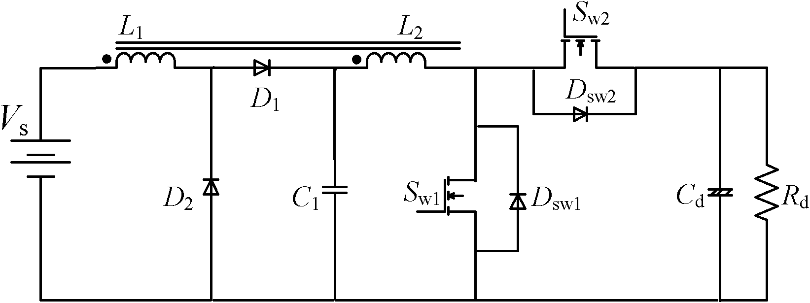
[0020] Such as figure 1 As shown, the bidirectional DC-DC converter of the present invention includes a coupled inductor L 1 , L 2 , two diodes D 1 、D 2 , a snubber capacitor C 1 , power supply V S , filter capacitor C d , load R d and two power switches S w1 , S w2 . Two coupled inductors are coupled to each other by sharing an inductor core. Coupled inductor L 1 The end with the same name is connected to the positive pole of the power supply, and the other end is connected to the diode D 1 anode, diode D 2 The cathode is connected to the diode D 1 Cathode and coupled inductor L 2 Connected to the terminal of the same name, the coupled inductor L 2 The other end is connected to the power switch tube S w1 Drain, S w2 source connected. S w1 source and capacitance C d , capacitance C 1 connected, the switching tube S w2 Drain and Capaci...


PUM


Abstract

A bidirectional DC-DC converter based on coupling inductors belongs to the technical field of converters. The converter comprises the two coupling inductors L1 and L2, two diodes D1 and D2, a buffer capacitor C1, a power source VS, a filter capacitor Cd, a load Cd, and two power switch tubes Sw1 and Sw2. The invention has the advantages as follows: by virtue of the coupling inductors, the step-up ratio of the converter is improved; leakage inductance energy of the coupling inductors is absorbed through the filter capacitor, so that the peak voltage stress of each switch tube can be effectively reduced; and since the diode D1 prevents the buffer capacitor C1 from discharging electricity to an input terminal, the energy (incl., leakage inductance energy) accumulated by the buffer capacitor C1 is totally transmitted to a load through the inductively-coupling inductors, and then the efficiency of the converter is improved.

Description

technical field [0001] The invention belongs to the technical field of converters, in particular to a bidirectional DC-DC converter based on coupled inductance. Background technique [0002] Bidirectional DC-DC converters are mainly used in applications such as electric vehicles, uninterruptible power supplies (UPS), aviation power systems, solar power systems, and shipboard power supplies. At present, in large-scale motor equipment, supercapacitors are mostly used as energy storage devices, and the bidirectional DC-DC converter is used to control, store and feed back the energy of braking and power generation of the motor to achieve the purpose of energy saving. [0003] At present, bidirectional DC-DC converters mostly adopt non-isolated BUCK / BOOST topology. Due to the limitation of topology, the main problem of bidirectional DC-DC converter is that the gain of boost mode is low. In order to improve its gain The voltage ratio needs to change the circuit topology, which wi...

Claims


Application Information

Patent Timeline
Patent Type & Authority Applications(China)
IPC IPC(8): H02M3/335H02J7/00
Inventor 褚恩辉张化光刘秀翀于万淼户伟玉金升王遨宇毋勐漾
Owner NORTHEASTERN UNIV
Why Eureka
Try Eureka