Downlink power control method and device applied to long term evolution (LTE) system

A power control and power technology, applied in power management, wireless communication, electrical components, etc., to achieve the effect of power control

Active Publication Date: 2011-07-06
DATANG MOBILE COMM EQUIP CO LTD
View PDF3 Cites 42 Cited by
  • Summary
  • Abstract
  • Description
  • Claims
  • Application Information

AI Technical Summary

Problems solved by technology

However, there are two problems in the existing scheme: 1) how to determine the power level of other downlink physical signals / physical reference signals except the physical channel / physical reference signal of the existing defined power allocation scheme, and notify the physical layer; 2) ) How to ensure that the downlink transmission power after power configuration is within the range allowed by the system, that is, how to protect the transmission power when the total power on one OFDM symbol is greater than the maximum transmission power of the device

Method used


Image

  • Downlink power control method and device applied to long term evolution (LTE) system
  • Downlink power control method and device applied to long term evolution (LTE) system
  • Downlink power control method and device applied to long term evolution (LTE) system

Examples


Embodiment 1

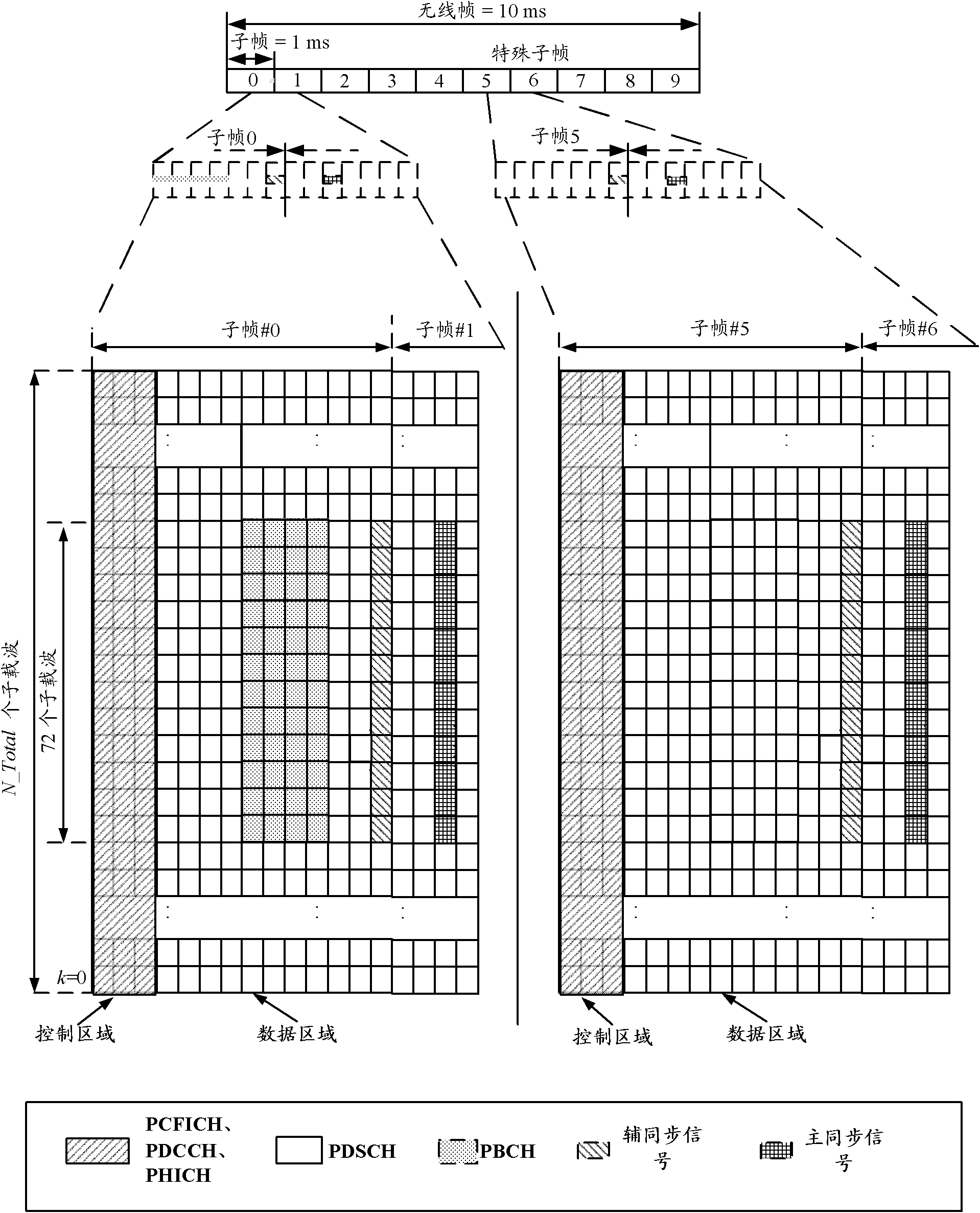
[0110] In this embodiment, the power protection scheme adopts the first mode, that is, the power protection scheme of RRC+MAC. Such as Figure 5 As shown, the first configuration module 501, the second configuration module 502, and the third configuration module 504 are located at the RRC layer; the power control module 503 is located at the MAC layer, and the MAC also has existing downlink scheduling and resource allocation for downlink scheduling and resource allocation module, and a module for assembling MAC packets.

[0111] In this embodiment, the power control method in this embodiment includes the following five steps, and the power control module 503 completes step 2, step 3 and step 4.

[0112] Step 1, the RRC layer and the MAC layer respectively perform relevant initialization operations, specifically including:

[0113] Step 1.1, the RRC layer initializes the following parameters:

[0114] 1) The first configuration module 501 configures the absolute power value ...

Embodiment 2

[0145] In this embodiment, the power protection scheme adopts the second mode, that is, the power protection scheme of RRC+MAC+PL (Physical Layer, Physical Layer). Such as Image 6 As shown, the first configuration module 501, the second configuration module 502 and the third configuration module 504 are located at the RRC layer; the maximum value determination module 51 in the power control module 503 and the ratio determination module in the power protection module 52 are located at the MAC layer, and the The power adjustment module 522 is set in the downlink resource mapping module for downlink resource mapping in the PL, the PL also includes a downlink transmitter for sending signals, and the MAC also has an existing downlink scheduling and resource allocation module for downlink scheduling and resource allocation, and Module for assembling MAC packets.

[0146] Embodiment 2 comprises 6 steps, wherein step 1 to step 3 are identical with embodiment 1.

[0147] Step 4, get...


PUM


Abstract

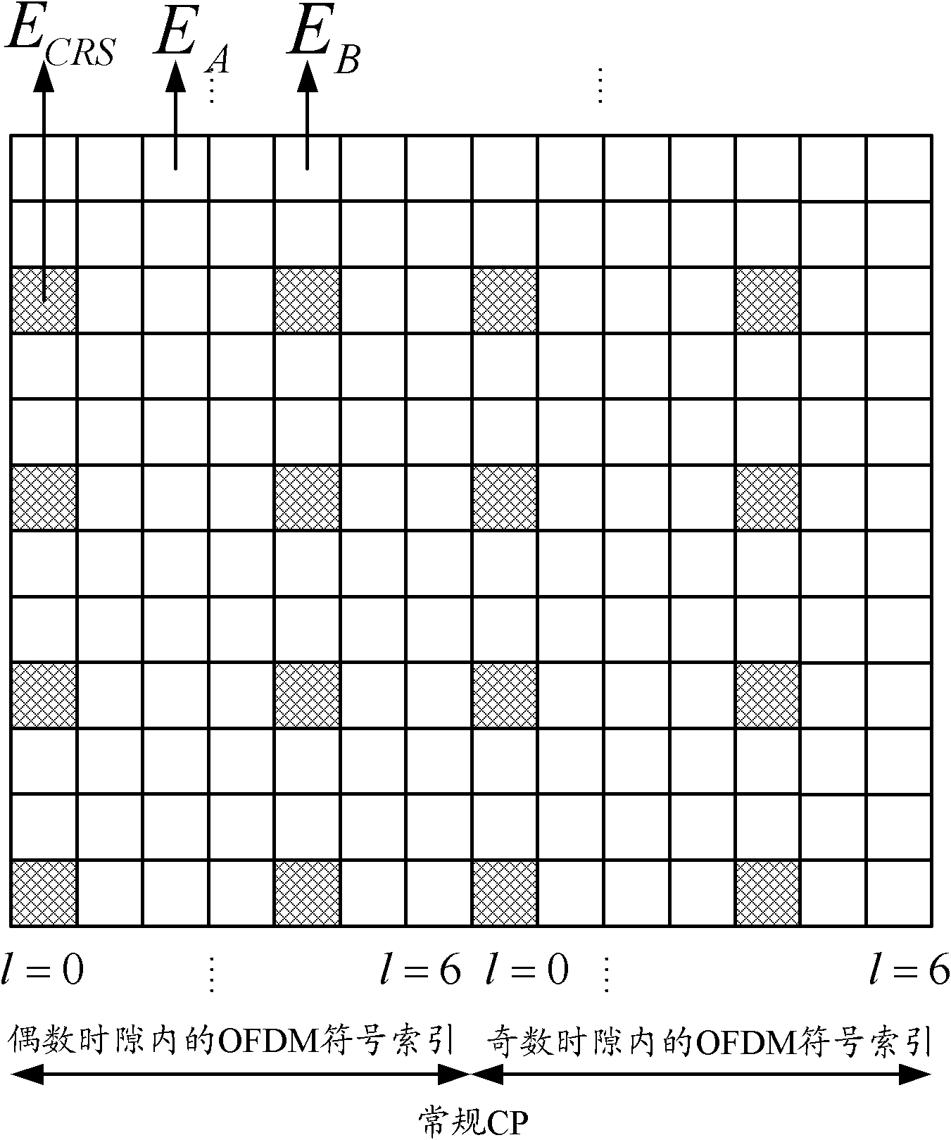
The invention discloses a downlink power control method and a downlink power control device applied to a long term evolution (LTE) system. The method comprises the following steps of: configuring an absolute power value ECRS_dBm for a resource element (RE) including a cell reference signal (CRS); configuring parameters indicating a transmission power of a same type for all downlink physical channels or downlink physical signals except the CRS according to the ECRS_dBm; and performing power control on the transmission of the downlink physical channels or the downlink physical signals according to the ECRS_dBm and the parameters indicating the transmission power. In the invention, the method for configuring the power value of the all downlink physical channels or the all downlink physical signals in the implementation of an LTE product is provided, so that the correct demodulation of receiving data by user equipment can be guaranteed, and the safety of network-side base station equipment can be guaranteed.

Description

technical field [0001] The present invention relates to the technical field of wireless communication, in particular to a downlink power control method and device applied to an LTE system. Background technique [0002] Power control is an important function in cellular mobile communications. Power control keeps the signal power received by the receiving end within an appropriate range, which not only compensates for channel fading, but also ensures that the transmission power will not be too large and affect the normal communication of users. It is one of the important measures to improve the performance of cellular systems. one. The goal of the downlink power control of the LTE (Long Term Evolution, Long Term Evolution) system is to reduce the transmission power of the downlink channel as much as possible under the premise of satisfying the user's reception quality, so as to achieve the purpose of alleviating inter-cell interference. [0003] The downlink power allocation...

Claims


Application Information

Patent Timeline
Patent Type & Authority Applications(China)
IPC IPC(8): H04W52/14H04W72/04
Inventor 任斌李琼
Owner DATANG MOBILE COMM EQUIP CO LTD
Why Eureka
Try Eureka