Method for optimizing linear array antenna radiation pattern
What is AI technical title?
AI technical title is built by Patsnap AI team. It summarizes the technical point description of the patent document.
A technology of antenna pattern and optimization method, applied in antennas, instruments, calculation models, etc., can solve problems such as limited adjustment of variable parameters, and achieve the effect of improving probability and speed
Inactive Publication Date: 2011-07-13
西安新海天通信有限公司
View PDF3 Cites 14 Cited by
Summary
Abstract
Description
Claims
Application Information
AI Technical Summary
This helps you quickly interpret patents by identifying the three key elements:
Problems solved by technology
Method used
Benefits of technology
Problems solved by technology
The existing direction map synthesis method based on genetic algorithm, according to the iterative optimization process of genetic algorithm, has limited adjustment of variable parameters, so it cannot flexibly solve the weight problem of compromise or priority of each index
Method used
Image
Click on the blue label to locate the original text in one second.
Reading with bidirectional positioning of images and text.
Examples
Embodiment 1
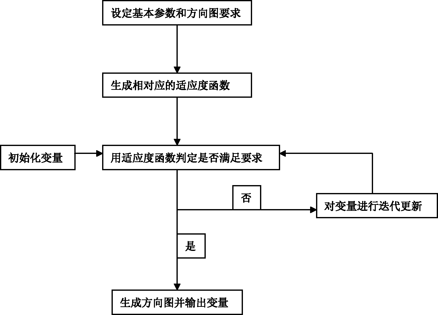
[0042] Step 1, set parameters
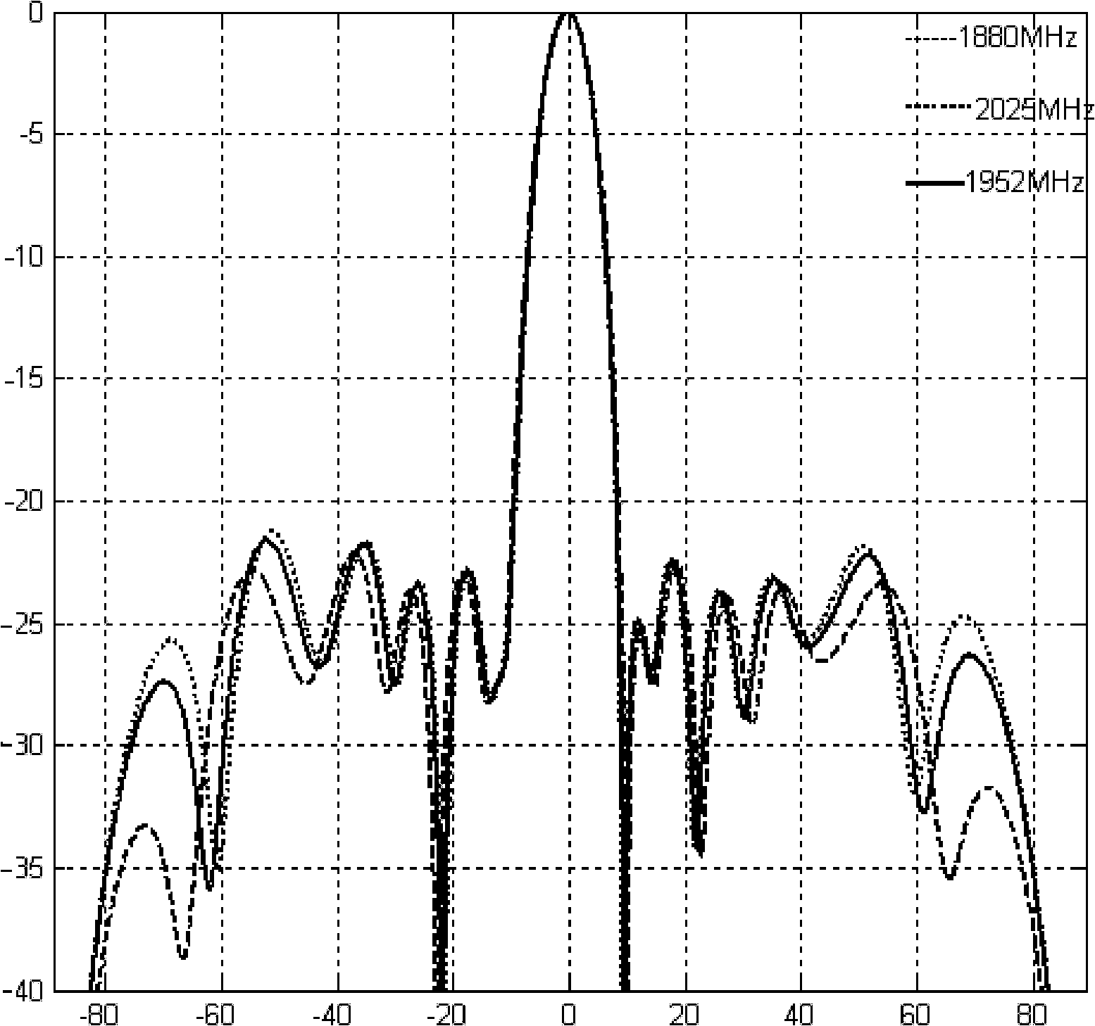
[0043] According to the requirements of the system, the number of array elements N=10, the operating frequency 1880MHz≤F≤2025MHz, the height of the array element H=30mm, the length of the array element arm L=30mm and the downtilt angle θ max =0°, the level value of the pattern requires that both the upper side lobe and the lower side lobe are suppressed below -20dB.
[0044] Step 2, generate the corresponding level suppression fitness function fitness according to the given level value requirements 1 , level filling fitness function fitness 2 and downtilt angle fitness function fitness 3 .
[0046] fitness 1 =∑(max(f(θ), f 0 (θ))-f 0 (θ)) m +∑abs(max(f(θ), f 0 (θ))-f 0 (θ))
[0047] fitness 2 =∑(min(f(θ), f 0 (θ))-f 0 (θ)) m +∑abs(min(f(θ), f 0 (θ))-f 0 (θ))
[0048] fitness 3 =(f(θ max )-f 0 (θ max )) m +|f(θ max )-f 0 (θ max )|;
[0049] Since the level value given by the s...
Embodiment 2
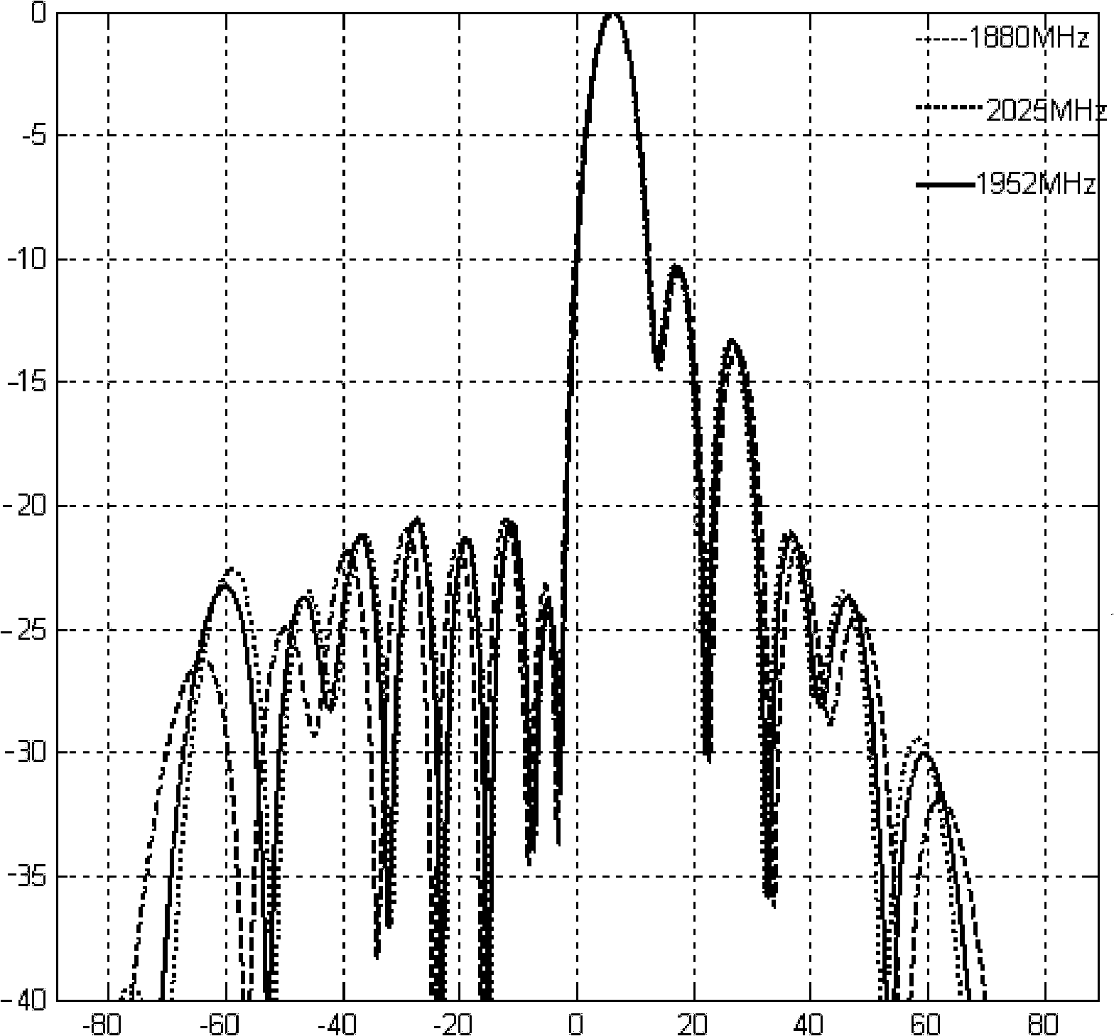
[0084] Step 1, set parameters.
[0085] According to the requirements of the system, the number of array elements N=10; the working frequency is 1880MHz≤F≤2025MHz; the height of the array element is H=30mm; max =6°; the unit spacing is specified as d(i)=115mm; the excitation amplitudes of 10 units are respectively given as: 1, 1, 1, 1, 1.414, 1.414, 1.414, 1.414, 1.414, 1.414; the pattern level The value requires that the upper side lobe be suppressed to below -20dB, and the first zero value of the lower side lobe is filled to above -15dB.
[0086] Step 2, generate the corresponding level suppression fitness function fitness according to the given level value requirements 1 , level filling fitness function fitness 2 and downtilt angle fitness function fitness 3 .
[0088] fitness 1 =∑(max(f(θ), f 0 (θ))-f 0 (θ)) m +∑abs(max(f(θ), f 0 (θ))-f 0 (θ))
[0089] fitness 2 =∑(min(f(θ), f 0 (θ))-f 0 (θ)) m +∑abs(min(f(θ), f 0...
PUM
Abstract
The invention discloses a method for optimizing a linear arrayantenna radiation pattern, which mainly solves the problems of low shaping and optimizing speed, low accuracy and low flexibility of the conventional antenna radiation pattern. The method comprises the following steps of: (1) setting parameters given by a system and a radiation pattern level value required by the system; (2) generating a level restraining fitness function, a level filling fitness function and a lower inclination angle fitness function according to the radiation pattern level value required by the system; (3) initializing excitation amplitude, an excitation phase and a unit distance parameter, and performing iterative optimization according to an optimizing formula until the requirement that the sum of values of the three fitness functions is equal to zero can be met; and (4) generating an antenna radiation pattern from the optimized excitation amplitude and / or the optimized excitation phase and / or the unit distance according to the theory of the array antenna radiation pattern so as to finish optimization on the radiation pattern. The method has advantages of high calculation speed, high accuracy and strong flexibility, and the optimized design, meeting the various system requirements, of the linear array antenna radiation pattern can be achieved.
Description
technical field [0001] The invention belongs to the technical field of antennas, relates to the shaping optimization of an antenna pattern, and can be used for pattern design of a linear array antenna. Background technique [0002] The antenna pattern is an index to examine the coverage effect of the antenna, and its pros and cons directly determine whether the wireless communication system can work normally. The process of solving the excitation amplitude, phase and element spacing of the array antenna according to the antenna index and beam shape required by the system is called pattern synthesis. The method of synthesizing the array antenna pattern is mainly to design the pattern of the alignment factor, and then finally solve the pattern of the antenna required by the project according to the principle of taking advantage of the pattern. In different applications, there are different requirements for the antenna pattern, and it becomes very important to synthesize a var...
Claims
Application Information
Patent Timeline
Application Date:The date an application was filed.
Publication Date:The date a patent or application was officially published.
First Publication Date:The earliest publication date of a patent with the same application number.
Issue Date:Publication date of the patent grant document.
PCT Entry Date:The Entry date of PCT National Phase.
Estimated Expiry Date:The statutory expiry date of a patent right according to the Patent Law, and it is the longest term of protection that the patent right can achieve without the termination of the patent right due to other reasons(Term extension factor has been taken into account ).
Invalid Date:Actual expiry date is based on effective date or publication date of legal transaction data of invalid patent.

