Light-emitting diode driving circuit

A technology of light emitting diodes and driving circuits, which is applied in the layout of electric lamp circuits, light sources, electric light sources, etc., can solve the problems of complicated circuits, rising design costs, and difficult control, and achieves the effect of simple driving circuit structure and cost reduction.

Inactive Publication Date: 2011-07-13
TOP VICTORY INVESTMENTS
View PDF4 Cites 40 Cited by
  • Summary
  • Abstract
  • Description
  • Claims
  • Application Information

AI Technical Summary

Problems solved by technology

[0005] However, the number of light strings that can be supported by commercially available dedicated LED controllers is fixed. With the increase in the number of light strings from 11 to 1m, multiple LED controllers need to be used in parallel. Communication and control will increase

Method used


Image

  • Light-emitting diode driving circuit
  • Light-emitting diode driving circuit
  • Light-emitting diode driving circuit

Examples


Embodiment Construction

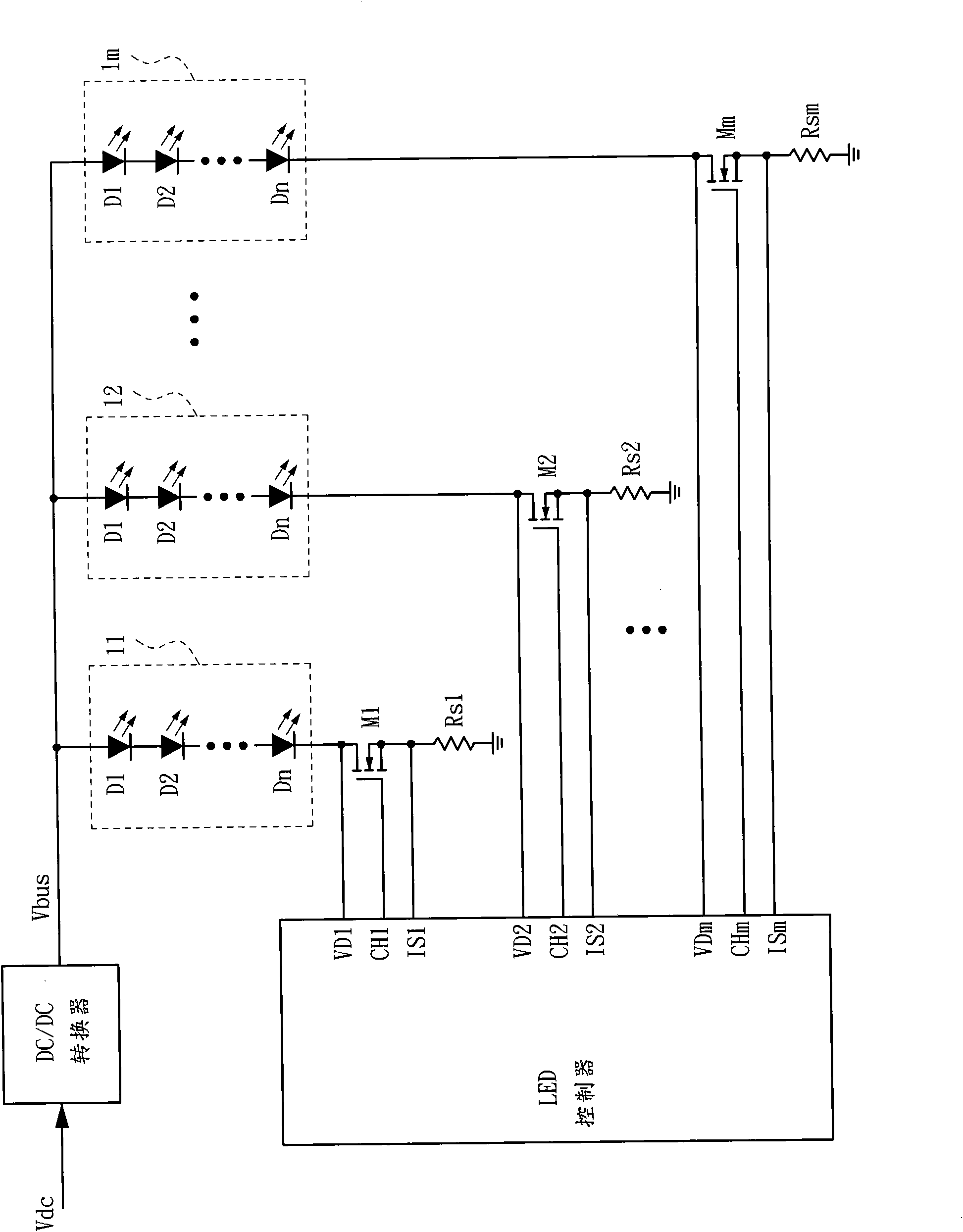
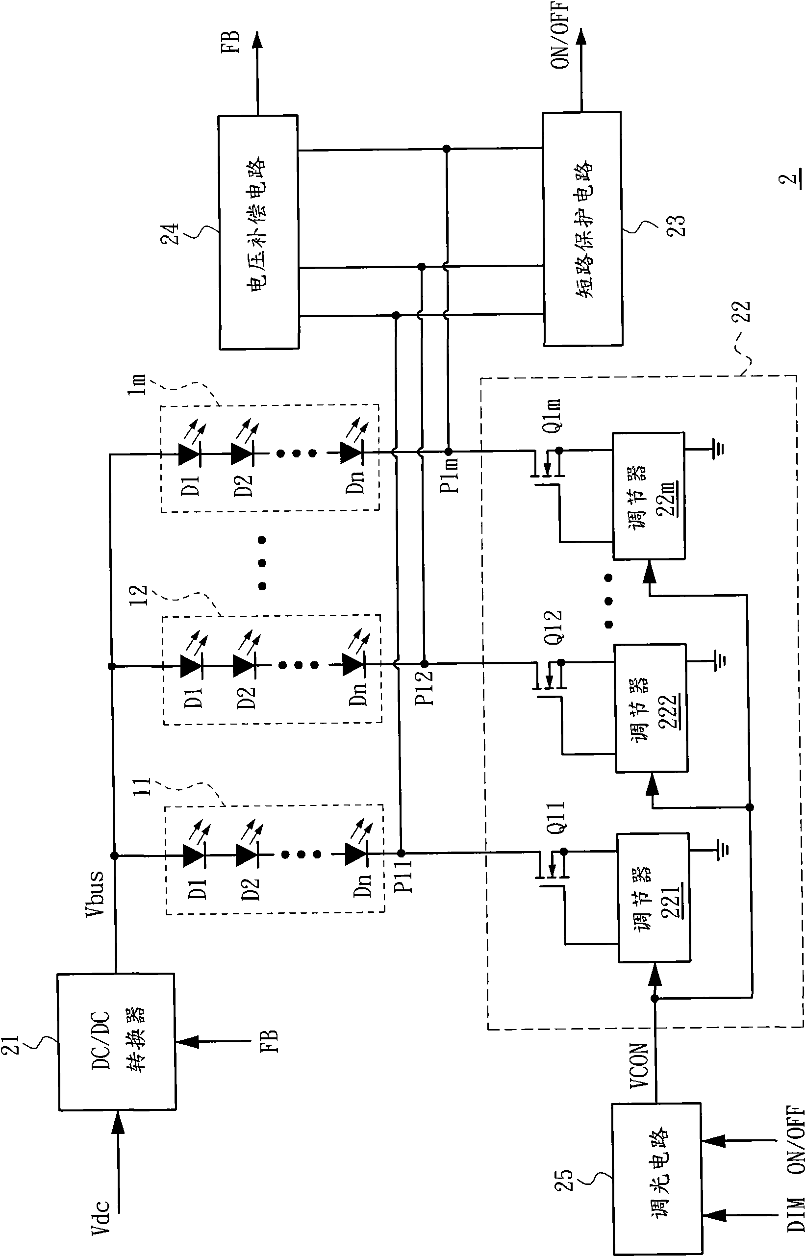
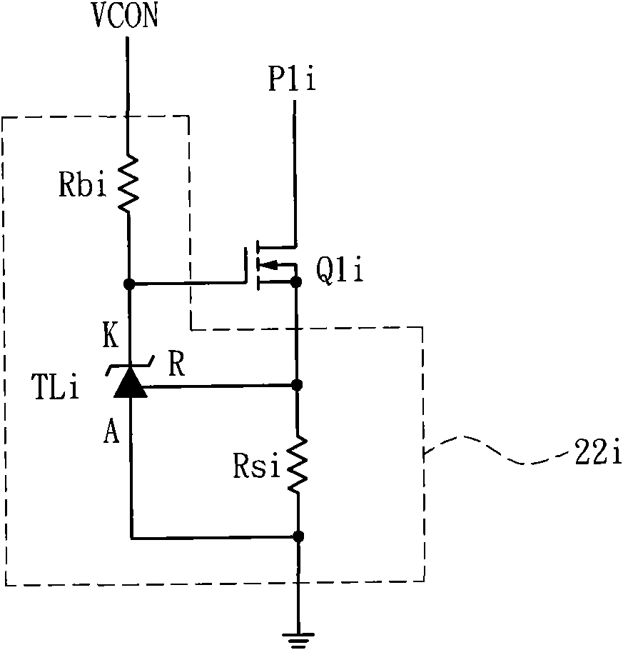
[0020] First of all, it should be noted that those skilled in the art should know that the switch or the switch circuit has a first terminal, a second terminal and a control terminal. The first type switch or switch circuit is turned on when the control terminal receives a high-level signal (that is, the first terminal and the second terminal are connected), and is not turned on when the control terminal receives a low-level signal (that is, the first terminal is connected). And the second terminal is disconnected); the second type switch or switch circuit is turned on when the control terminal receives a low-level signal (that is, the first terminal and the second terminal are connected) and when the control terminal receives a high-level signal No conduction (that is, the first terminal and the second terminal are disconnected). The first type of switch or switch circuit can be implemented with NPN bipolar transistors (or N-channel field effect transistors), the first termina...


PUM


Abstract

The invention provides a light-emitting diode (LED) driving circuit. A second end of each light string is connected with a current balancer in series to perform self-feedback control so as to adjust the current passing through each light string respectively; a voltage compensation circuit is added to finely adjust the voltage of each light string to ensure that each light string with different straight-forward voltage can be completely illuminated; besides, a short circuit protective circuit is added to ensure that the LED driving circuit is turned off when the LED short circuit happens in the light string, so the light string is protected from being burnt out by excess current. The LED driving circuit does not need to adopt a special LED controller, and the framework of the driving circuit is quite simple, so that the cost can be greatly reduced.

Description

Technical field [0001] The present invention relates to a light source driving technology, and particularly relates to a light-emitting diode (Light-Emitting Diode, LED for short) driving circuit. Background technique [0002] Ideally, the forward rated voltage of the LED is, for example, 3.3V, but there must be errors in the component. For example, in the case of a 5% error, the actual forward rated voltage of the LED will be between 3.135V and 3.465V. Therefore, even if the light bar is formed by the same number and the same type of LEDs coupled in series, the forward conduction voltage of each light string (which is the ratio of the forward conduction voltage of each LED connected in series) The sum) will still be different from each other. If the same bias voltage is applied to each light string, when each light string is turned on, the current flowing through each light string will be different because of the actual forward conduction voltage. Of course, the brightness prov...

Claims


Application Information

Patent Timeline
IPC IPC(8): H05B37/02
Inventor 林立韦李振强李吉欣
Owner TOP VICTORY INVESTMENTS
Why Eureka
Try Eureka