
Method for controlling inverter-integrated electric compressor for vehicle air-conditioning system

A technology of electric compressors and vehicle air conditioners, which is applied in the direction of machines/engines, liquid variable displacement machines, pump control, etc., can solve the problems of cooling power drop, increase in overall size and number of components, increase in production and other costs, etc. Achieve the effect of increasing energy consumption efficiency and preventing joint damage

Inactive Publication Date: 2011-07-13
DOOWON TECHN COLLEGE +1
View PDF5 Cites 2 Cited by
  • Summary
  • Abstract
  • Description
  • Claims
  • Application Information

AI Technical Summary

Problems solved by technology

[0012] However, in the embodiment where the heat sink is used to cool the inverter, since the area of ​​the heat sink needs to be increased to sufficiently cool the high-temperature inverter, the overall size and number of components increase, increasing production and other costs
In addition, when the driving operation of the electric compressor is stopped, although the inverter can be avoided from overcurrent and overheating damage, the cooling power is greatly reduced, and the cooling of the car will also stop when the driving operation of the electric compressor is stopped.

Method used


Image

  • Method for controlling inverter-integrated electric compressor for vehicle air-conditioning system
  • Method for controlling inverter-integrated electric compressor for vehicle air-conditioning system
  • Method for controlling inverter-integrated electric compressor for vehicle air-conditioning system

Examples


Embodiment Construction

[0026] An embodiment of the present invention will be described in more detail below with reference to the accompanying drawings.

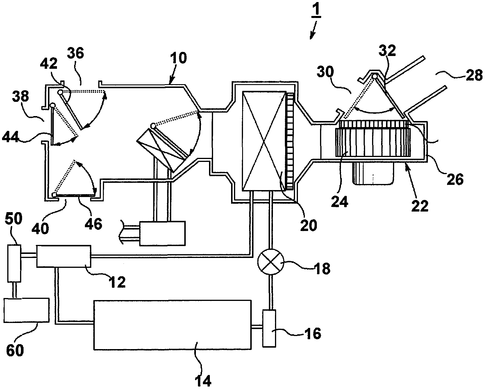
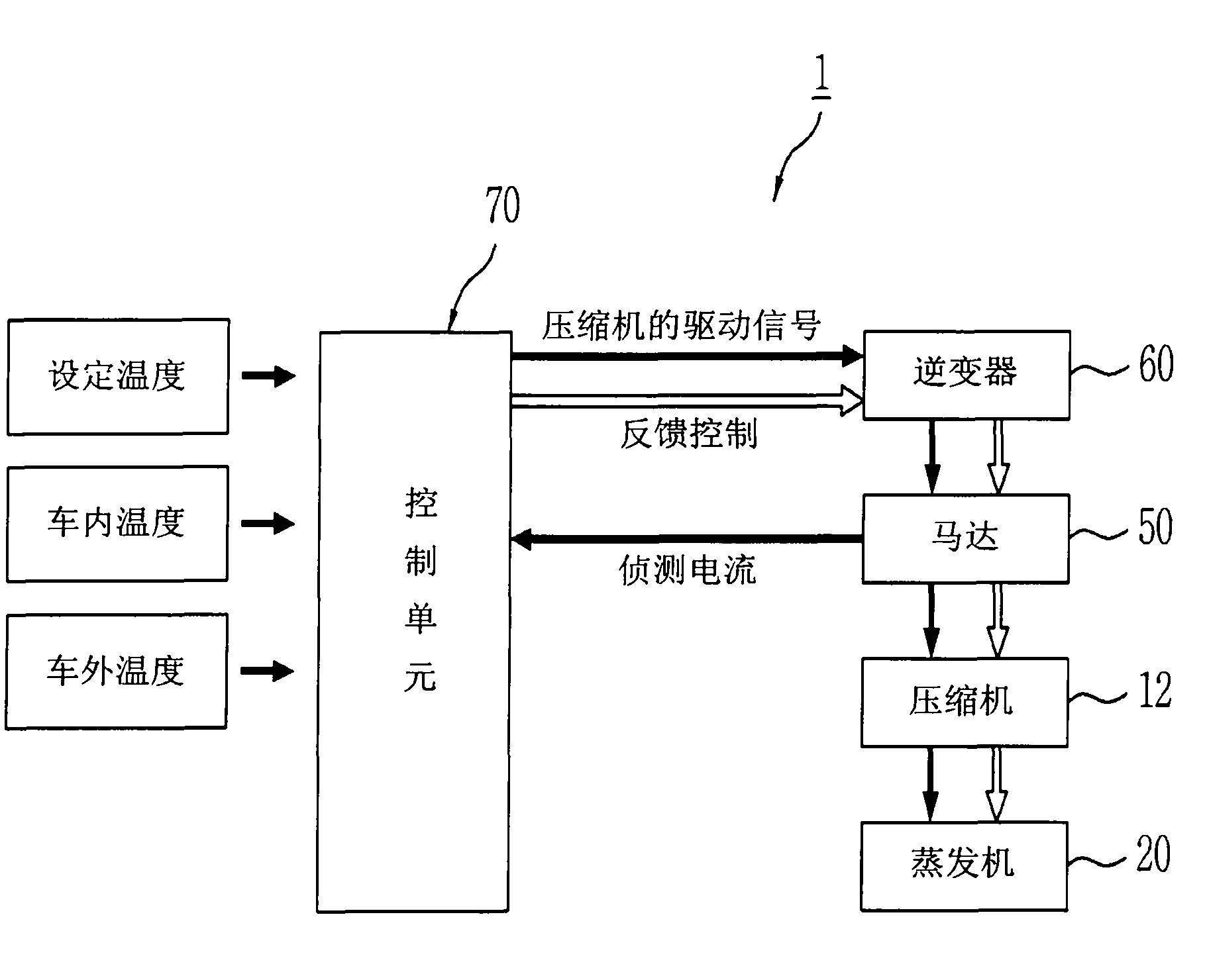
[0027] figure 2 is a block diagram of a vehicle air-conditioning system according to an embodiment of the present invention, and its reference figure 1 illustrate.

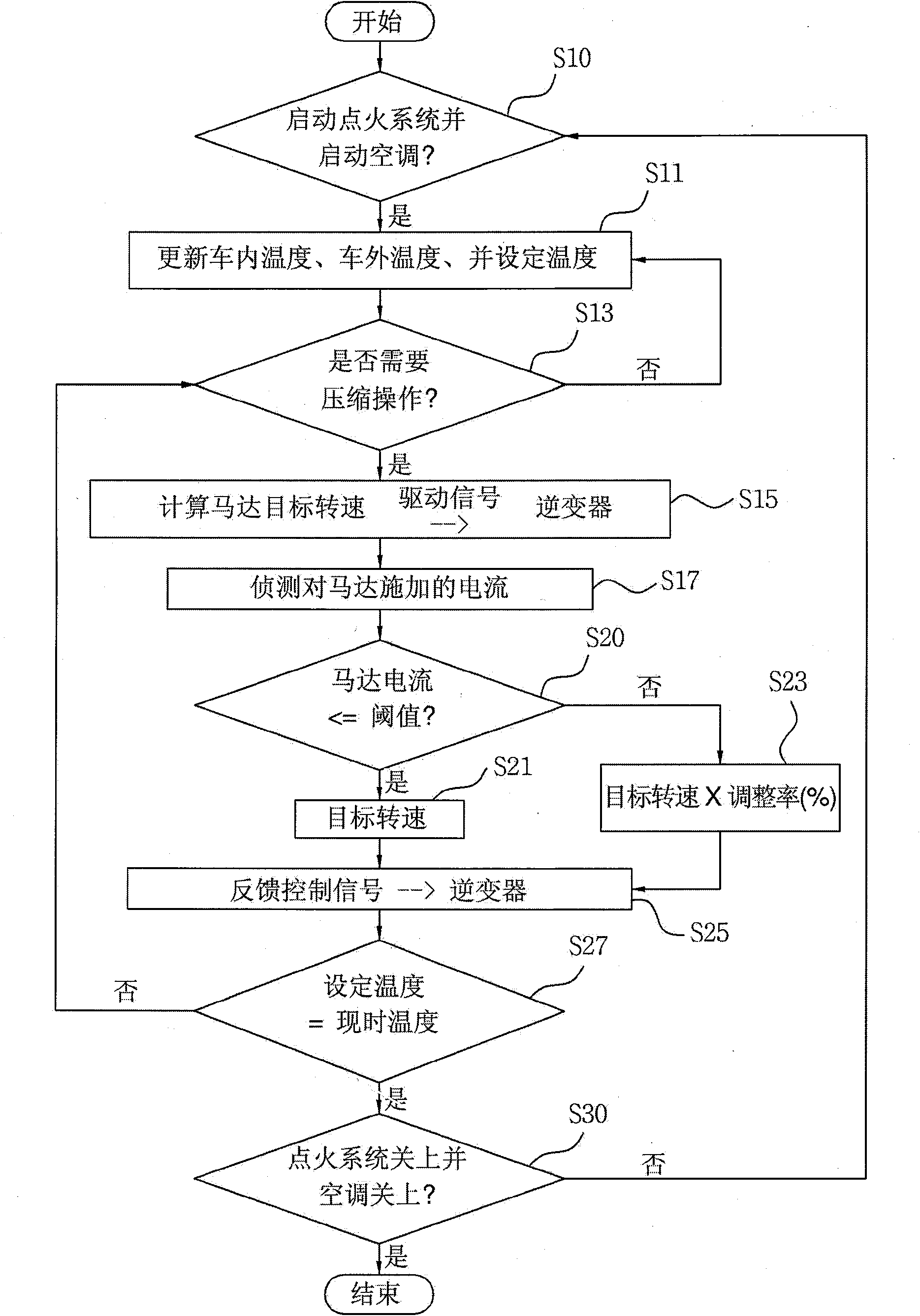
[0028] Such as figure 1 and figure 2 As shown, in the vehicle air conditioning system 1 according to the embodiment of the present invention, when the air conditioner of the vehicle is activated and the user inputs the temperature set by the user to the control unit 70, the vehicle temperature measured by the vehicle interior temperature sensor and the vehicle exterior temperature sensor The interior and exterior temperatures are input to the control unit 70 .

[0029] Afterwards, the control unit 70 calculates the difference between the ideal temperature set by the user and the temperature inside the vehicle, and determines whether to drive the electric compressor 12 .

[0030...


PUM


Abstract

The present invention relates to a method for controlling an inverter-integrated electric compressor for a vehicle air-conditioning system, and more particularly, to a method for controlling an inverter-integrated electric compressor for a vehicle air-conditioning system which can reduce only the RPM of a motor without stopping an inverter and thus maintain a rated power and torque when a compression load of an air-conditioner is large and an over-current occurs in the inverter, exceeding the torque generated from the motor of the electric compressor, and which can reduce the RPM, which is an angular speed, and increase a torque, and thus continuously providing drivers with a comfortable environment with a vehicle air-conditioner even when the torque of the motor exceeds the maximum level due to overload, and which can reduce risks of the inverter and the electric compressor and thus prevent secondary damage. The method for controlling an inverter-integrated electric compressor for a vehicle air-conditioning system comprises: the first step of calculating a target RPM of a motor for driving an inverter-integrated electric compressor in a vehicle air-conditioning system; the second step of checking whether or not the current applied to the motor driven according to the target RPM exceeds the threshold value preset in a control unit; and the third step of performing a feedback control for reducing the target RPM and reducing the current if the current applied to the motor exceeds the threshold value, and of rotating the motor according to the target RPM if the current does not exceed the threshold value.

Description

technical field [0001] The invention relates to a control method for an inverter-integrated electric compressor of a vehicle air-conditioning system, in particular to a control method that can prevent overcurrent from being generated due to the load of the inverter driving the electric compressor, and control the electric compressor without stopping the vehicle air-conditioner. In the case of the system, the control method of the inverter integrated electric compressor of the vehicle air-conditioning system that reduces the rotating speed is used to prevent the air-conditioning system from being damaged due to overcurrent. Background technique [0002] In general, an air conditioning system for a vehicle is used to introduce air from outside or inside a vehicle, heat or cool the introduced air, and then blow the heated or cooled air into the vehicle to heat or cool the interior of the vehicle. [0003] One technique that only performs cooling operations is described in more ...

Claims


Application Information

Patent Timeline
Patent Type & Authority Applications(China)
IPC IPC(8): B60H1/32F04B49/06
CPCB60H1/3222B60H1/00428F04B49/06F04B2203/0209F04B2203/0201Y02T10/88F04B35/04F05B2210/12Y10S417/00
Inventor 李建祜具仁会李侹景
Owner DOOWON TECHN COLLEGE
Learn More