Conical surface mechanical sealing device

A mechanical seal device and conical surface technology, applied in the direction of engine seals, mechanical equipment, engine components, etc., can solve the problems of increased friction and wear, circumferential pressure pulsation, and the mechanical seal on the end face needs to be strengthened, etc. , Good resistance to torsional deformation of shaft section

Inactive Publication Date: 2011-07-20
XIHUA UNIV
View PDF4 Cites 13 Cited by
  • Summary
  • Abstract
  • Description
  • Claims
  • Application Information

AI Technical Summary

Problems solved by technology

However, for the self-centering performance of the axes of the two seal rings during the seal installation and operation, as well as the torsional deformation of the seal end surface along the shaft section, or the bending deformation of the main shaft of the unit where the moving rin...

Method used


Image

  • Conical surface mechanical sealing device
  • Conical surface mechanical sealing device
  • Conical surface mechanical sealing device

Examples


Embodiment 1

[0047] Embodiment 1: see figure 1 , figure 2 , image 3

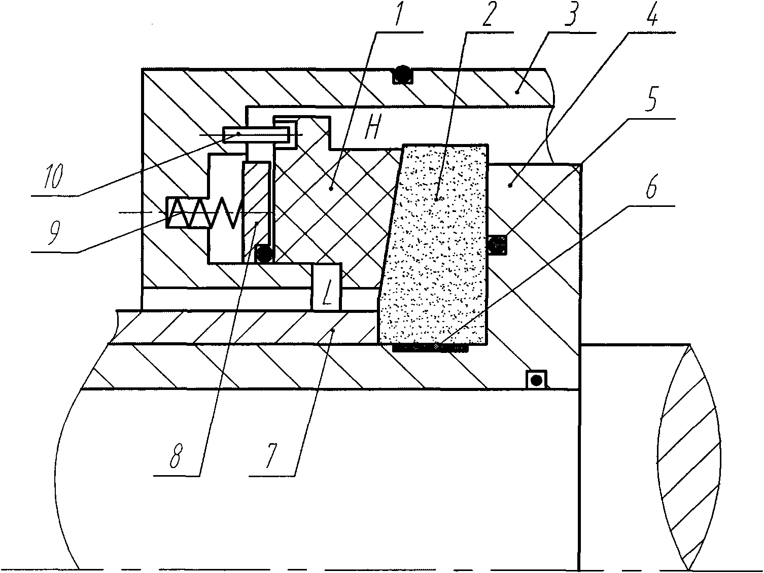
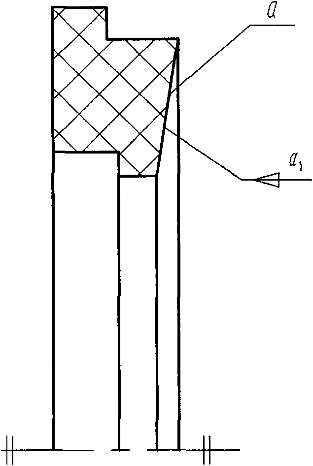
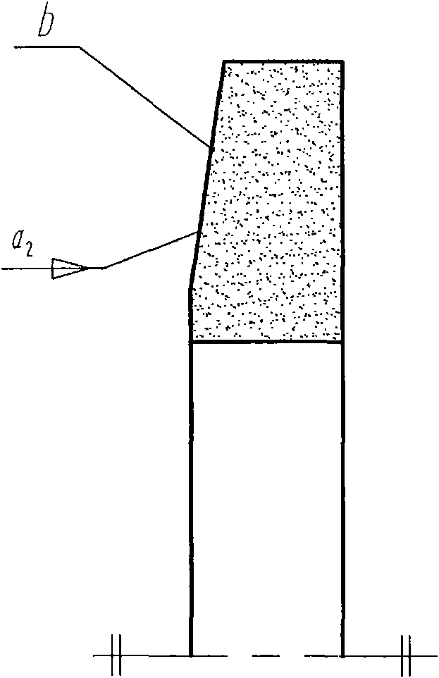
[0048] figure 1 It is a structural schematic diagram of Embodiment 1 of the present invention. The tapered mechanical seal device includes a stationary ring 1 with a tapered surface a, a rotating ring 2 with a tapered surface b, a stationary ring seat 3, a shaft sleeve 4, an "O" ring 5, a tolerance ring 6, and a compression sleeve 7. Push ring 8, spring 9, anti-rotation pin 10, etc. The feature of this embodiment is that the two sealing surfaces (namely: the cone surface a and the cone surface b) are in direct contact.

[0049] according to figure 1 , figure 2 , image 3 , the tapered surface a on the stationary ring 1 is a tapered hole surface, and its taper is α 1 , the conical surface b on the rotating ring 2 is a conical surface, and its taper is α 2 , the relationship between the two tapers is: α 1 ≥α 2 . The stationary ring 1 and the rotating ring 2 are installed face-to-face and coaxially to form a...

Embodiment 2

[0051] Embodiment 2: see Figure 4

[0052] Figure 4 It is a structural schematic diagram of Embodiment 2 of the present invention. The tapered mechanical seal device includes a stationary ring 1 with a tapered surface a, a rotating ring 2 with a tapered surface b, a stationary ring seat 3, a shaft sleeve 4, an "O" ring 5, a tolerance ring 6, and a compression sleeve 7. Push ring 8, spring 9, anti-rotation pin 10, etc. The characteristic of this embodiment is that the two sealing surfaces (namely: the cone surface a and the cone surface b) are separated by a small gap h0.

[0053] according to Figure 4 , the tapered surface a on the stationary ring 1 is a tapered hole surface, and its taper is α1 , the conical surface b on the rotating ring 2 is a conical surface, and its taper is α 2 , the relationship between the two tapers is: α 1 ≥α 2 . The stationary ring 1 and the rotating ring 2 are installed face-to-face and coaxially to form a tapered sealing surface, and a ...

Embodiment 3

[0055] Embodiment 3: see Figure 5 , Image 6

[0056] Figure 5 , Image 6 It is a structural schematic diagram of Embodiment 3 of the present invention. The tapered mechanical seal device includes a stationary ring 1 with a tapered surface a, a rotating ring 2 with a tapered surface b, a stationary ring seat 3, a shaft sleeve 4, an "O" ring 5, a tolerance ring 6, and a compression sleeve 7. Push ring 8, spring 9, anti-rotation pin 10, etc. The characteristic of this embodiment is that a fluid dynamic pressure groove c is provided on the conical sealing surface b of the moving ring.

[0057] according to Figure 5 , the tapered surface a on the stationary ring 1 is a tapered hole surface, and its taper is α 1 , the conical surface b on the rotating ring 2 is a conical surface, and its taper is α 2 , the relationship between the two tapers is: α 1 ≥α 2 . The stationary ring 1 and the rotating ring 2 are installed face-to-face and coaxial to form a tapered sealing su...


PUM


Abstract

The invention relates to a conical surface mechanical sealing device, which is characterized in that: a mechanical sealing static ring 1 is provided with a conical surface a; a rotary ring 2 is provided with a conical surface b; the conical surface a and the conical surface b are paired to form a sealing surface; and the sealing surface is that the conical surface a and the conical surface b are directly contacted, or are separated by a micro gap. Compared with the conventional mechanical sealing device, the conical surface mechanical sealing device has the advantages of higher automatic centering property and higher capability of resisting the torsional deformation of a shaft section and the bending deformation of a main shaft of a unit due to two sealing rings. The conical surface mechanical sealing device is suitable for the shaft end sealing of various rotary machines.

Description

technical field [0001] The invention belongs to the shaft end seal of a rotary machine, and particularly relates to a cone mechanical seal device, which can be used for various types of rotary machines such as compressors, expanders, separators, pumps, and reactors. Shaft end seal. Background technique [0002] Mechanical seals are widely used on shaft ends of many rotating machines. Due to the complexity of their working conditions, in-depth research on mechanical seals will be a long-term, arduous and must be continuously advanced process, especially the shape of the sealing mating surface and its performance. Research has always been the focus and difficulty of sealing technology research. The research and development of the shaft end dynamic seal of rotating machinery has mainly gone through two processes: [0003] 1. Radial seal [0004] Early rotary machinery spindle seals used labyrinth seals. Labyrinth seals had a large amount of leakage and could only be used in ...

Claims


Application Information

Patent Timeline
IPC IPC(8): F16J15/34F16J15/46F16J15/16
Inventor 王和顺董霖朱维兵王强
Owner XIHUA UNIV
Why Eureka
Try Eureka