Plunger type pneumatic quick change coupler
A plunger type and head technology, applied in the field of quick connection of gas pipelines, can solve problems such as complex structure, short service life, and large material consumption
- Summary
- Abstract
- Description
- Claims
- Application Information
AI Technical Summary
Problems solved by technology
Method used
Image
Examples
Embodiment 1
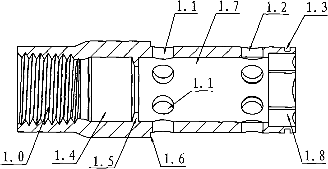
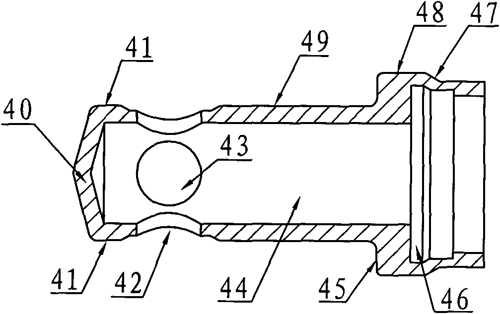
[0028] Embodiment 1: A kind of plunger type pneumatic quick-change joint, such as figure 1 As shown, it includes the intake joint 1 connected to the intake pipe, the intake sealing ring 2, the sealing retaining ring 3, the valve core 4, the locking steel ball 5, the moving sliding sleeve 6, the shaft retaining ring 7, the air outlet seal Ring 8, spool spring 9 and sliding sleeve spring 10, the intake sleeve 1 is a casing structure, such as figure 2 As shown, the left section is the connecting section, and the right section is the matching section. On the left end of the outer circle of the matching section of the intake joint 1, six pressure relief holes 1.1 are uniformly arranged along the circumference, and the function of the pressure relief holes 1.1 is It is when the air-inducing plug Plug is inserted into the quick-change joint to produce a pressure relief effect, which is more conducive to the easy insertion of the air-inducing plug Plug. On the right end of the outer ...
Embodiment 2
[0029] Embodiment 2: A kind of plunger type pneumatic quick-change joint, such as Figure 5 As shown, its structure is similar to that of Embodiment 1, the difference is that: in the inner hole of the air intake sleeve 1, such as Figure 6 As shown, the air intake sealing groove 1.9 is provided at the position corresponding to the sealing retaining ring 3, and the sealing retaining ring 3 is clamped in the intake sealing groove 1.9 so that the sealing retaining ring 3 realizes the axial limit to prevent excessive air source pressure. As a result, the intake sealing ring 2 compresses the sealing retaining ring 3 and retracts excessively to generate air leakage.
Embodiment 3
[0030] Embodiment 3: A kind of plunger type pneumatic quick-change joint, such as Figure 7 As shown, its structure is similar to that of Embodiment 1, the difference is that the positioning bead hole 13 and the pressure relief hole 1.1 are evenly arranged on the left end of the outer circle of the fitting section of the air inlet sleeve 1 along the circumferential direction, and the positioning bead The hole 13 and the pressure relief hole 1.1 are distributed along the circumferential interval. The positioning bead 11 is placed in the positioning bead hole 13. The positioning bead 11 is radially limited by the spring chamber 61 of the moving sliding sleeve 6. The left side of the positioning bead 11 Axially limit the sealing retaining ring 3, so that the sealing retaining ring 3 realizes axial limiting, and prevents air leakage caused by excessive retraction caused by the intake sealing ring 2 pressing the sealing retaining ring 3 due to excessive air source pressure.
PUM
 Abstract
Description
Claims
Application Information
 - R&D
- Intellectual Property
- Life Sciences
- Materials
- Tech Scout
- Unparalleled Data Quality
- Higher Quality Content
- 60% Fewer Hallucinations
Browse by: Latest US Patents, China's latest patents, Technical Efficacy Thesaurus, Application Domain, Technology Topic, Popular Technical Reports.
© 2025 PatSnap. All rights reserved.Legal|Privacy policy|Modern Slavery Act Transparency Statement|Sitemap|About US| Contact US: help@patsnap.com


