
Ejector throttling air supply system and heat pump or refrigeration system air supply method
A technology of air supply system and ejector, applied in the field of heat pump or refrigeration system air supply and throttling air supply system, can solve the problems of uneconomical small air-conditioning heat pump system, difficulty in processing and manufacturing of expander, large throttling loss, etc. Simple structure, low cost, and the effect of increasing air supply
- Summary
- Abstract
- Description
- Claims
- Application Information
AI Technical Summary
Problems solved by technology
Method used
Image

Examples
Embodiment 1
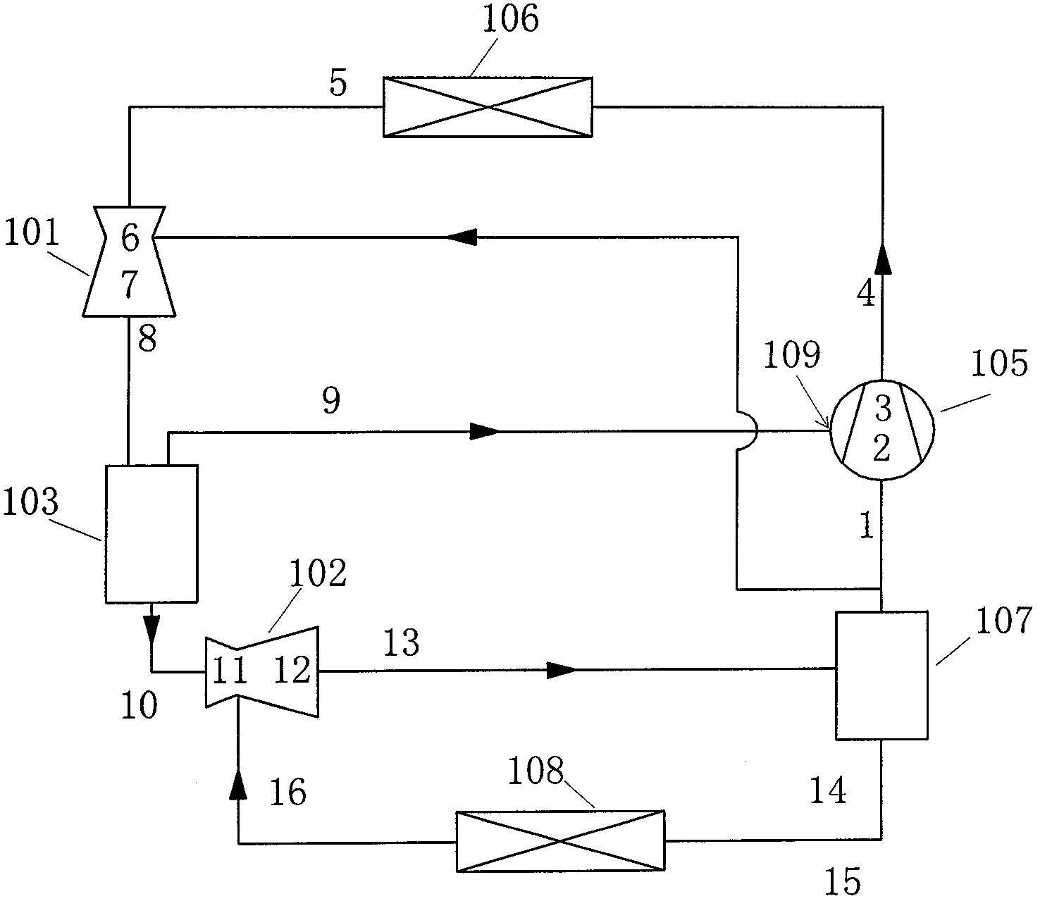
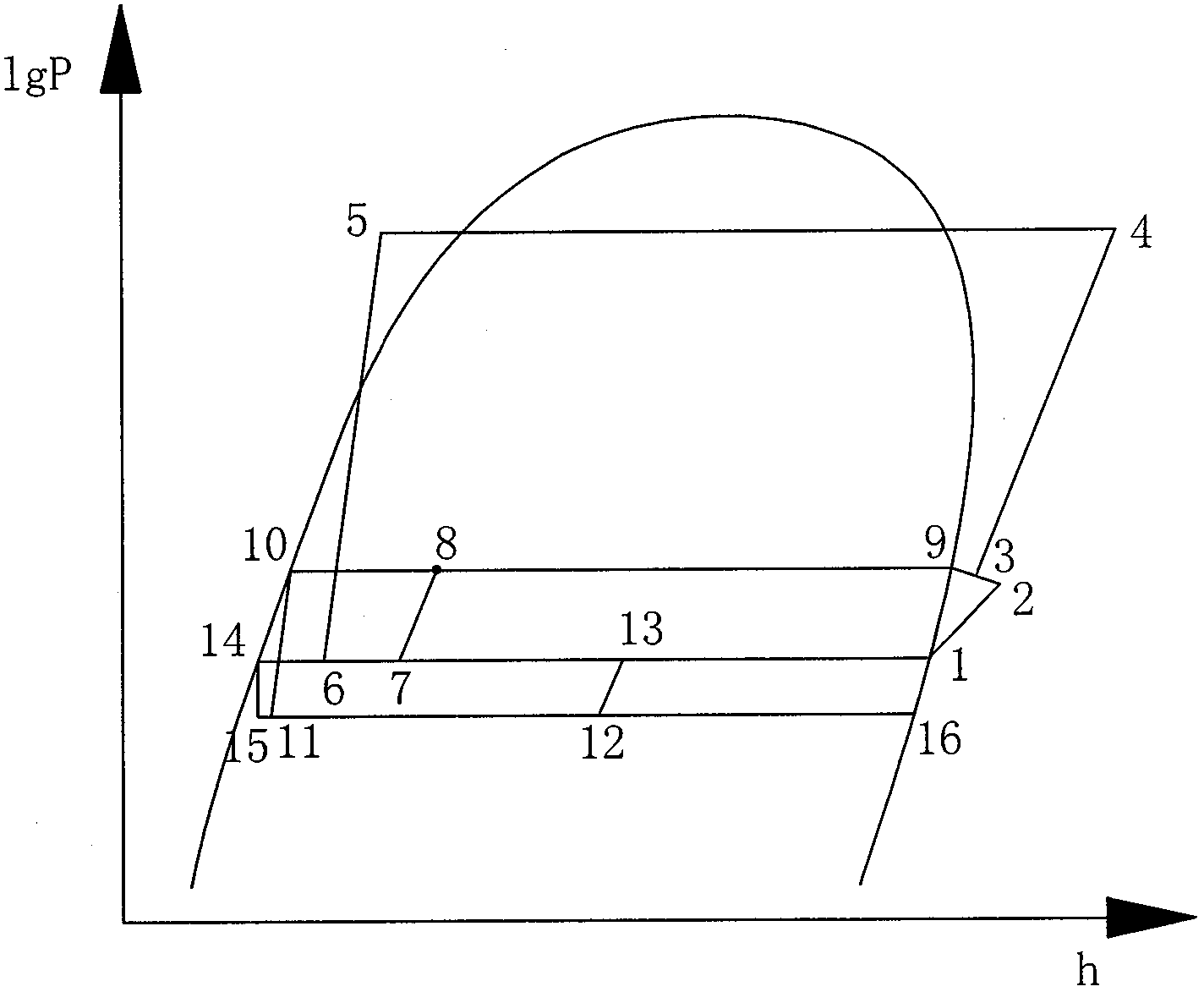
[0028] For example one, please refer to image 3 , The system consists of a compressor 105, a condenser 106, a first ejector 101, a flasher 103, a second ejector 102, a gas-liquid separator 107, a throttling device, and an evaporator 108. The high-temperature and high-pressure refrigerant vapor 4 discharged from the compressor transfers heat to the brine through the condenser 106 and can be used for room heating or as domestic hot water. The high-pressure refrigerant liquid 5 coming out of the condenser 106 enters the first ejector 101 as a working fluid, injects the low-temperature and low-pressure refrigerant vapor 1 coming out of the gas-liquid separator 107, and is throttled, mixed, and diffused by the first ejector 101. After being pressurized, it enters the flasher 103, and the medium-pressure refrigerant vapor at the upper part enters the air supply port 109 of the compressor, and the medium-pressure refrigerant liquid at the lower part is used as the working fluid of t...
Embodiment 2
[0029] Embodiment 2 Please refer to Figure 5 , similar to Embodiment 1, the economizer 104 system is used to replace the flasher 103 system, and a part of the subcooled liquid refrigerant 5 coming out of the condenser 106 is throttled by the first injector 101 6 and mixed with the injection fluid 7, diffused 8 and then enter the economizer 104 to absorb heat and become refrigerant vapor 9 and then enter the air supply port of the compressor.
[0030] see Figure 6 In the third embodiment, on the basis of the second embodiment, two-stage compression is used to replace the original quasi-two-stage compression system. A small part of the refrigerant vapor 1 at the outlet of the gas-liquid separator 107 is ejected by the first injector 101, and the main part is ejected by the first ejector 101. The low-pressure compressor 112 sucks in, compresses and discharges 2 and the refrigerant vapor 9 from the economizer 104 mixes 3 and enters the suction port of the high-pressure compress...
PUM
 Abstract
Description
Claims
Application Information