
Multi-cavity baffle type electrolytic milling and grinding complicated machining tool cathode and method

A tool cathode and compound processing technology, which is applied in the field of multi-cavity baffle type electrolytic milling and grinding compound processing tool cathodes, can solve problems such as short circuit workpieces, increased electrolyte pressure, and holes in the processing gap

Active Publication Date: 2017-06-30
NANJING UNIV OF AERONAUTICS & ASTRONAUTICS
View PDF6 Cites 19 Cited by
  • Summary
  • Abstract
  • Description
  • Claims
  • Application Information

AI Technical Summary

Problems solved by technology

[0005] The cathode of the ordinary internal spray electrolytic milling and grinding compound processing tool is a hollow single cavity structure with multiple uniformly distributed liquid outlets on the bottom side wall. When using the common internal spray liquid electrolytic milling and grinding compound processing tool cathode , due to being blocked by the workpiece, the pressure of the electrolyte in the outlet hole facing the workpiece increases, causing most of the electrolyte to be ejected from the low-pressure outlet in the opposite direction of the cathode movement of the electrolytic milling and grinding composite processing tool, by The knowledge of flow field design in electrolytic machining shows that at this time, the electrolyte supply in the processing area is insufficient, and the processing heat and electrolytic products cannot be discharged in time, which may easily cause short circuits and workpiece burns; at the same time, when the electrolyte is sprayed from the processing gap, Based on the design knowledge of the electrolytic machining flow field, due to the sudden expansion of the flow channel area, it is easy to cause cavities in the machining gap, and it is also easy to cause short circuits and workpiece burns.
These two kinds of defects on the cathode of ordinary internal spray electrolytic milling and grinding composite processing tools will lead to poor processing stability and reduced processing accuracy, which limits the further development of this technology

Method used


Image

  • Multi-cavity baffle type electrolytic milling and grinding complicated machining tool cathode and method
  • Multi-cavity baffle type electrolytic milling and grinding complicated machining tool cathode and method
  • Multi-cavity baffle type electrolytic milling and grinding complicated machining tool cathode and method

Examples


Embodiment Construction

[0025] The present invention will be further described below in conjunction with accompanying drawing:

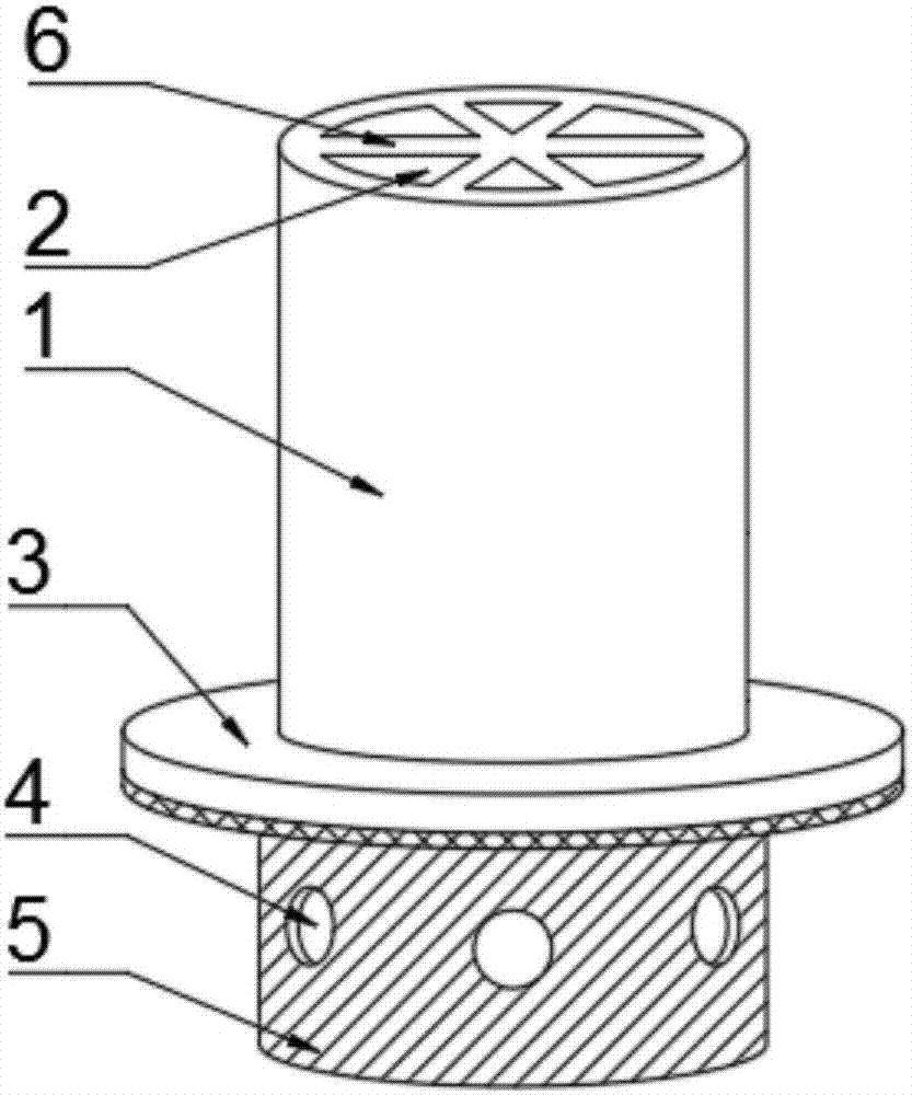
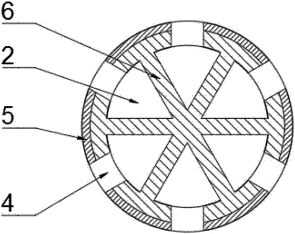
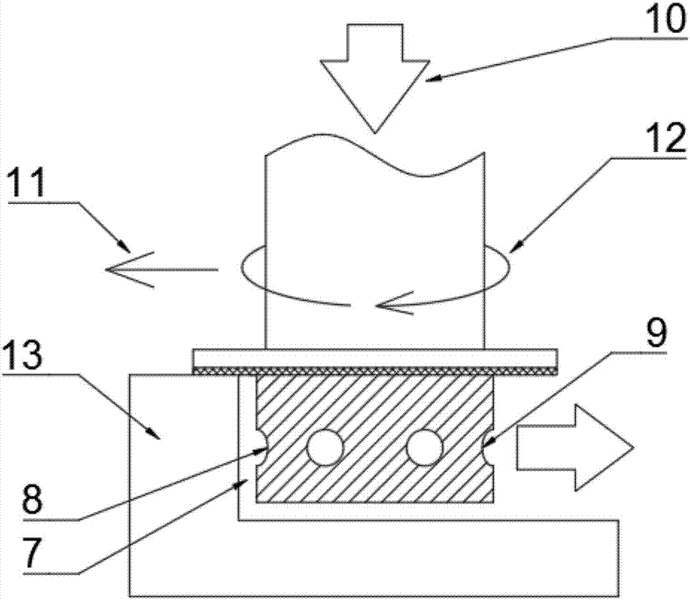
[0026] Such as figure 1 and figure 2 As shown, the cathode of a multi-cavity baffle plate type electrolytic milling and grinding compound processing tool proposed by the present invention includes a tool cathode base 1, the inside of the tool cathode base 1 is a central blind hole, and the cylindrical surface of the lower part of the cathode has an annular baffle 3, uniform Arrange liquid outlet holes 4 and diamond abrasive grain layer (5); it is characterized in that: the above-mentioned central blind hole is evenly divided into several fan-shaped blind hole cavities 2 by several axial partition plates 6; the fan-shaped blind hole cavities 2 divide the above-mentioned outlet The liquid holes 4 are evenly divided into several groups, and each fan-shaped blind hole cavity 2 communicates with a group of liquid outlet holes; the above-mentioned annular baffle 3 is located ab...


PUM


Abstract

The invention relates to a multi-cavity baffle type electrolytic milling and grinding complicated machining tool cathode and a method and belongs to the field of electrolytic milling and grinding complicated machining. According to the multi-cavity baffle type electrolytic milling and grinding complicated machining tool cathode and the method, by arranging a plurality of sector-shaped blind hole cavities in the tool cathode, and arranging an annular baffle above a cathode diamond abrasive particle layer, the defect that supplied liquid in a machining gap is not sufficient is overcome, the flow field uniformity is improved, and the stability and the machining precision of electrolytic milling and grinding complicated machining are effectively improved.

Description

technical field [0001] The invention relates to a cathode of a multi-cavity baffle type electrolytic milling and grinding compound processing tool and a method thereof, belonging to the field of electrolytic milling and grinding compound processing. Background technique [0002] With the development of science and technology, a large number of high-temperature alloys, titanium alloys and other metal materials are used in modern aviation, aerospace, shipbuilding and other industrial fields. For example, GH4169 alloy accounts for 34%, 56% and 57% of the total weight of CF6 engine, CY2000 engine and PW4000 engine respectively; titanium alloy accounts for 41% of the total materials used in the fourth-generation fighter F-22, etc. However, due to the inherent characteristics of these materials, such as poor thermal conductivity, high strength, and high hardness, the temperature in the processing area is high during machining, and the cutting force is large, which easily causes to...

Claims


Application Information

Patent Timeline
Patent Type & Authority Applications(China)
IPC IPC(8): B23H5/08B23H5/10
CPCB23H5/08B23H5/10
Inventor 付书星李寒松牛屾曲宁松
Owner NANJING UNIV OF AERONAUTICS & ASTRONAUTICS
Learn More