Single-sided corrugated plate type pulsating heat pipe

A technology of pulsating heat pipes and corrugated plates, applied in indirect heat exchangers, lighting and heating equipment, electrical components, etc., can solve problems such as complex processes, weak capillary action, and unsatisfactory heat transfer performance, and achieve wide source of materials , low price, excellent heat transfer effect

Inactive Publication Date: 2012-05-02
CHANGSHA UNIVERSITY OF SCIENCE AND TECHNOLOGY
View PDF6 Cites 0 Cited by
  • Summary
  • Abstract
  • Description
  • Claims
  • Application Information

AI Technical Summary

Problems solved by technology

The circular shape has weak capillary action. If you want to increase the capillary action, you need to process microgrooves in the circular channel, which is a complicated process.
The channels are also independent and sealed, and the heat transfer performance of the heat pipe cannot be improved by increasing the frequency of the change of the vapor and liquid plugs
[0013] Judging from the above-mentioned published technical documents, due to the limitations of the working mechanism adopted or the structure of the existing technologies or patents, their heat transfer performance has not yet reached better, and they cannot meet the increasingly stringent requirements. Harsh air conditioning ventilation energy recovery and the need for heat dissipation and cooling of electronic components

Method used


Image

  • Single-sided corrugated plate type pulsating heat pipe
  • Single-sided corrugated plate type pulsating heat pipe
  • Single-sided corrugated plate type pulsating heat pipe

Examples


Embodiment 1

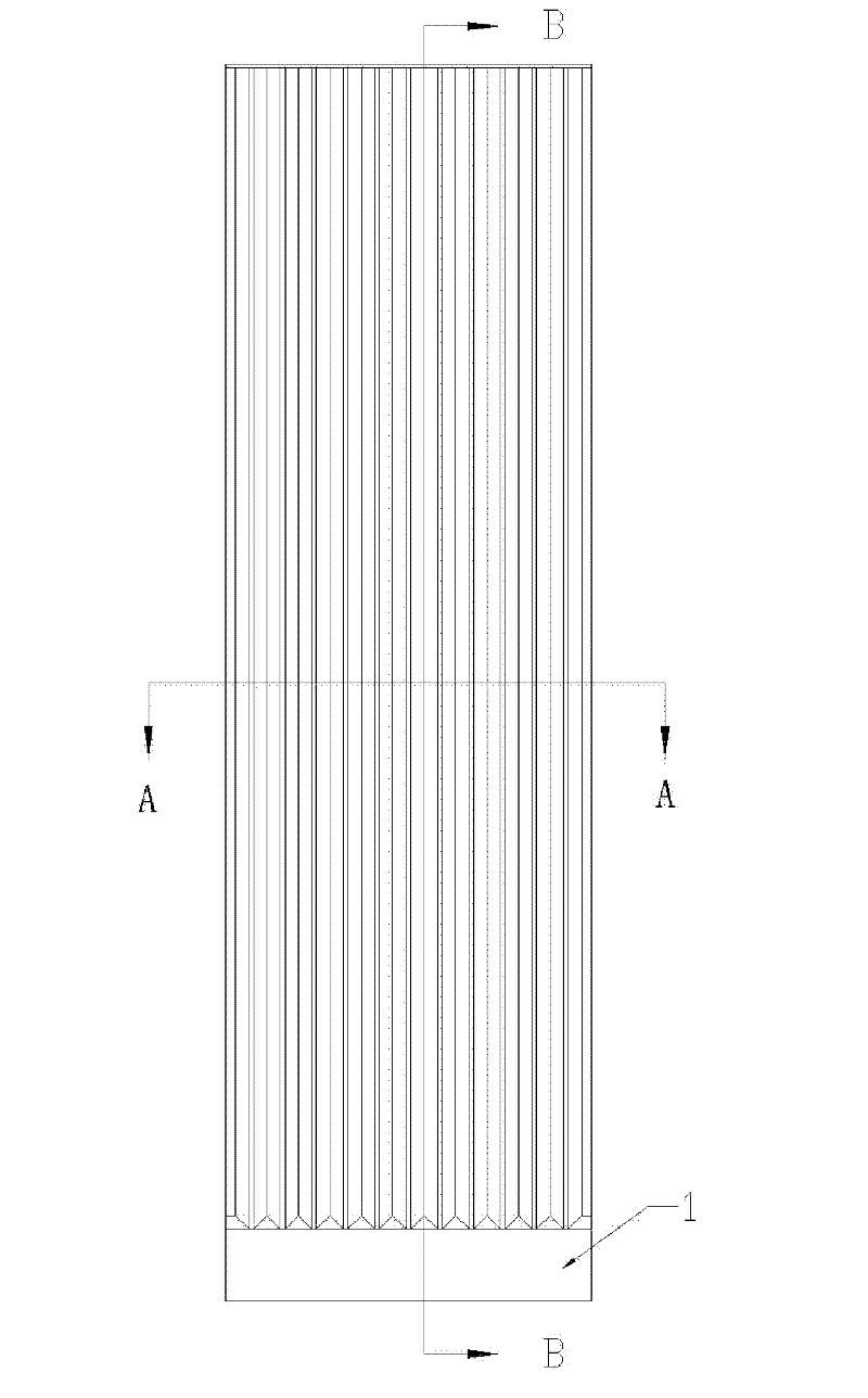
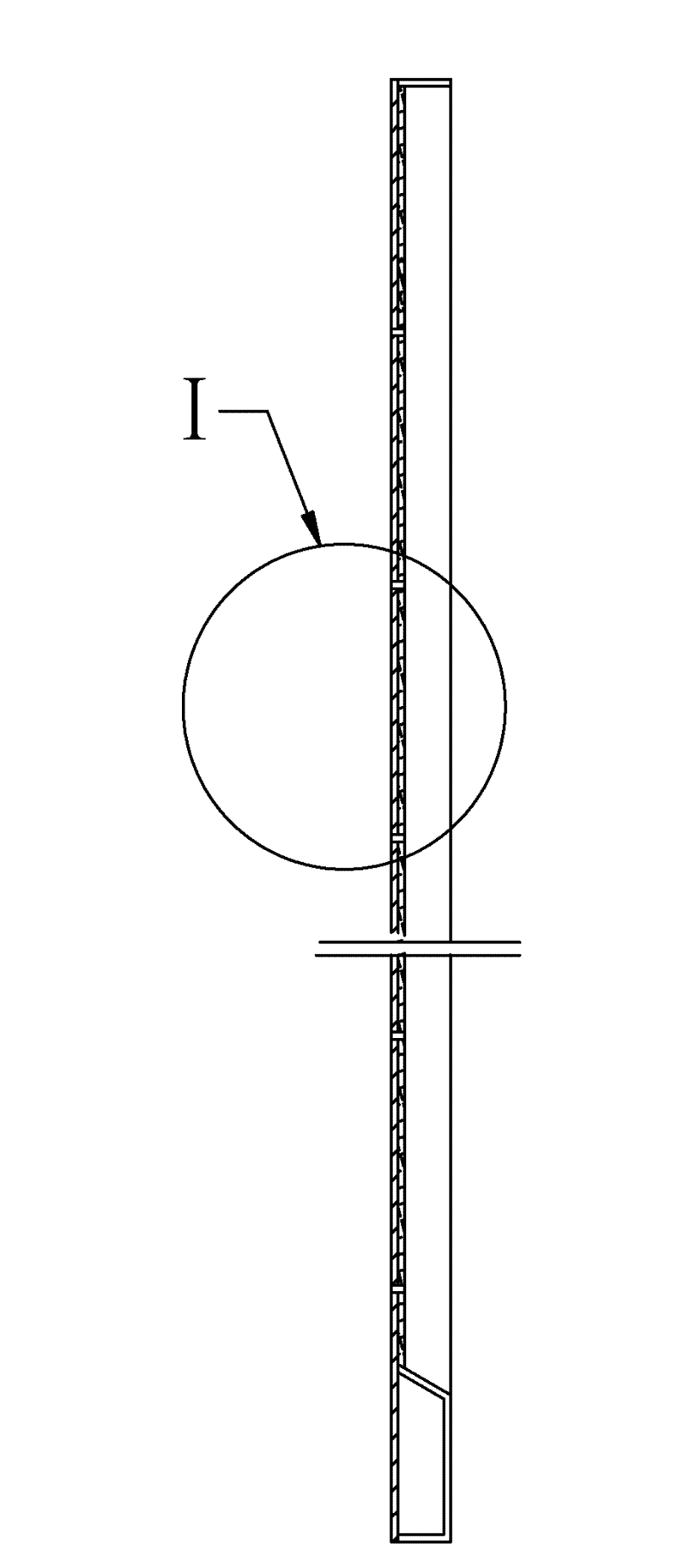
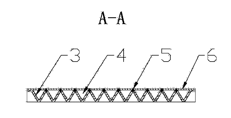
[0046] See attached figure 1 , 2 , 3, 4. The single-sided corrugated plate type pulsating heat pipe of the present invention includes a bottom plate 6, a wave plate 3, and a first communication cavity 1, and is characterized in that: the bottom plate 6 is a flat metal plate; one end of the bottom plate 6 is provided with a The first communication cavity 1 connected; the wave plate 3 is a curved plate formed by a periodic zigzag shape; the baffle plate is a flat metal plate; the two ends along the extending direction of the waves of the wave plate 3 and the The bottom plate 6 is sealed and connected, one end perpendicular to the extending direction of the wave of the wave plate 3 is sealed and connected with the first communication chamber 1, and the other end is sealed and connected with the bottom plate 6; the wave plate 3 is connected between two adjacent troughs A plurality of pulsating channels 4 perpendicular to the extension direction of the wave plate waves are formed...

Embodiment 2

[0049] See attached Figure 5 , 6 , the single-sided corrugated plate type pulsating heat pipe of the present invention includes a bottom plate 6, a wave plate 3, a first communication cavity 1, and a second communication cavity 2, and it is characterized in that: the bottom plate 6 is a plane metal plate; There is a first communication cavity 1 and a second communication cavity 2 that are sealed and connected with the bottom plate 6, and the wave plate 3 is a curved plate formed by a periodic zigzag shape; along the extension direction of the waves of the wave plate 3 Both ends are in sealing connection with the bottom plate 6, one end perpendicular to the extending direction of the waves of the wave plate 3 is in sealing connection with the first communication cavity 1, and the other end is in sealing connection with the second communication cavity 2, and the wave A plurality of pulsating channels 4 perpendicular to the extension direction of the waves of the wave plate are...


PUM


Abstract

The invention discloses a single-sided corrugated plate type pulsating heat pipe which comprises a bottom plate, a corrugated plate and a first communication cavity and is characterized in that: the bottom plate is a plane metal plate; one end of the bottom plate is provided with the first communication cavity in sealed connection with the bottom plate; the section of the corrugated plate is of acontinuous triangular shape, sinusoidal shape or other periodical curve shape; the two ends along the extension direction of the wave of the corrugated plate are in sealed connection with the bottom plate; one end vertical to the extension direction of the wave of the corrugated plate is in sealed connection with the first communication cavity, and the other end is in sealed connection with the bottom plate; two adjacent troughs of the corrugated plate are welded on the bottom plate through spot welding to form multiple pulsating channels vertical to the extension direction of the wave of thecorrugated plate; and adjacent channels are communicated through hair cracks. The equivalent coefficient of heat conductivity of the single-sided corrugated plate type pulsating heat pipe is two orders of magnitude higher than that of an aluminum extruded radiator and 2-3 times higher than that of the related flat heat pipe; and the single-sided corrugated plate type pulsating heat pipe can be horizontally mounted and is particularly suitable for recycling the ventilation energy of an air conditioner as well as radiating and cooling electronic devices.

Description

technical field [0001] The invention discloses a single-sided corrugated plate type pulsating heat pipe. It belongs to the technical field of heat exchange equipment. It is suitable for energy recovery of air-conditioning ventilation and heat dissipation and cooling of electronic devices. Background technique [0002] With the development of the economy, air conditioners are used more and more widely, but the energy consumption and air quality are increasingly bothering consumers. According to the "Indoor Air Quality Standards", in order to ensure the air quality, it is necessary to exhaust to the outside and send fresh air to the room. The incoming fresh air must be processed by the air conditioning unit to meet the requirements, while the exhaust air is already processed air, both of which consume energy. If the exhaust and fresh air can perform an energy exchange when entering and leaving the room, the load on the air conditioning unit will be greatly reduced and a lar...

Claims


Application Information

Patent Timeline
Patent Type & Authority Patents(China)
IPC IPC(8): F28D15/02H01L23/427
CPCF28D15/0266
Inventor 夏侯国伟张敏
Owner CHANGSHA UNIVERSITY OF SCIENCE AND TECHNOLOGY
Why Eureka
Try Eureka