

Side wall air inlet/outlet infrared air sensor
A gas sensor and sensor technology, applied in the fields of instruments, scientific instruments, color/spectral characteristic measurement, etc., can solve the problems affecting the popularization and application of infrared gas sensors, difficult engineering realization, long response time, etc. The effect of time reduction and response time reduction
- Summary
- Abstract
- Description
- Claims
- Application Information
AI Technical Summary
Problems solved by technology
Method used
Image

Examples
Embodiment Construction
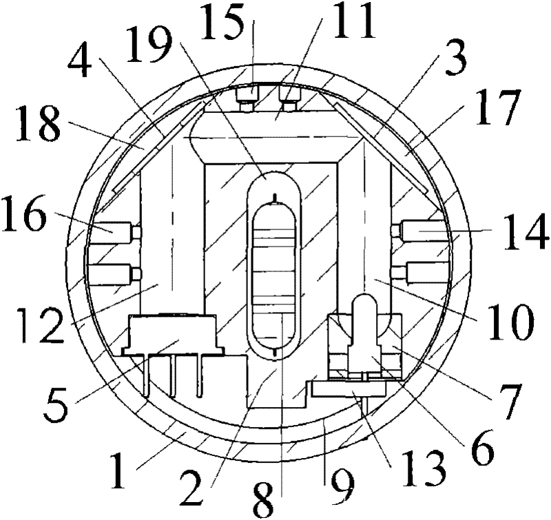
[0032] figure 1 It shows the structure inside the sensitive head of the infrared gas sensor with gas inlet / outlet through the side wall provided by the embodiment of the present invention. Dust cover 1 is a cylinder with an outer diameter of 40mm, an inner diameter of 34.5mm, and a height of 18mm made by sintering 60-80 mesh stainless steel powder and a stainless steel shell; dust cover 1 is embedded with a cylinder with a diameter of 34mm and a height of 16mm Shaped brass cavity 2; the right end of the cavity 2 is provided with a first through hole 10 at the right end with a diameter of 5mm, and a condenser lens 7 is arranged at the rear end of the first through hole 10 at the right end, and an infrared light source 6 is installed in the condenser lens 7, and the first through hole at the right end 10 The side wall is provided with at least 2 ventilation holes 14 with a diameter of 1-3 mm; the front end of the cavity 2 is provided with a front end second through hole 11 with ...
PUM
 Abstract
Description
Claims
Application Information