
Battery and battery pack

A technology of batteries and batteries, which is applied to battery components, secondary batteries, circuits, etc., can solve problems such as short service life, reduced service life, and low safety, and achieve long service life, good heat dissipation effect, and safety sex high effect

Active Publication Date: 2011-07-20
王为希
View PDF3 Cites 1 Cited by
  • Summary
  • Abstract
  • Description
  • Claims
  • Application Information

AI Technical Summary

Problems solved by technology

The current battery casing adopts a square structure, and the battery with this structure has the defect of poor heat dissipation effect, and it is also not conducive to arrangement and assembly into groups
[0004] 2. The sealing performance is also one of the main technical indicators of the battery. A battery with poor sealing performance has low safety and short service life.
The disadvantages of this structure are: since there is no special protective part at the end of the battery, parts such as conductive strips and poles are easily polluted by moisture, dust, etc., which will affect the normal operation of the battery and reduce its service life. In severe cases, it will cause Battery short circuit, misoperation, etc.
At present, there are some defects in the battery assembly process: for example, battery assembly is time-consuming and laborious; after the battery is disassembled, it cannot be assembled again, so the battery is scrapped and wastes resources; special machines need to be configured, which increases the cost of assembly, etc.

Method used


Image

  • Battery and battery pack
  • Battery and battery pack
  • Battery and battery pack

Examples


Embodiment 1

[0050] Embodiment 1: as Figure 1-4 As shown, the battery includes a casing 1 and a cell 2 , the casing 1 is cylindrical, and the casing 1 contains the cell 2 . Openings are formed at both ends of the casing 1 to lead out the positive and negative electrodes of the battery respectively. The structures of the two ends are the same or symmetrical, and the structure of one end will be described below.

[0051] The opening of the housing is covered by the end cover 3, the middle part of the end cover 3 passes through the pole 4, and the two are sealed and fitted. The inner side of the pole 4 is connected to the cell 2 through the pole lug 5 , the pole 4 and the pole lug 5 are connected by bolts, and the outside of the pole 4 is screwed to the end cover 3 by the nut 6 . The outer end of the pole 4 is also connected to the conductive strip 8 through the nut 7 .

[0052] The two ends of the housing 1 respectively form an annular notch 11 along the inner wall, which is used for embe...

Embodiment 2

[0056] Embodiment 2: as Figure 8-11 As shown, the battery includes a casing 1, which is cylindrical, and contains an electric cell 2 inside the casing 1, and the middle part of the electric cell 2 supports an inner support tube 3 along the axial direction. Openings are formed at both ends of the casing 1 to lead out the positive pole and the negative pole of the battery respectively. The structures of the two ends of the battery are the same or symmetrical, and the structure of the negative pole will be described in detail below.

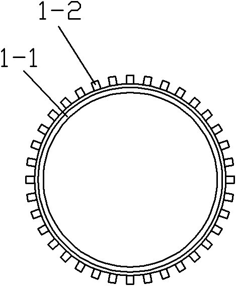
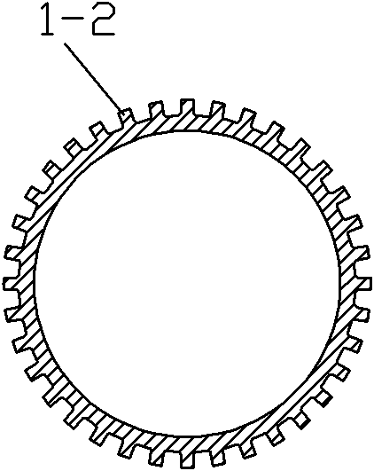
[0057] An annular notch 1 - 1 is formed along the inner wall at the end of the housing 1 , which is used for sealing and matching with the end cap 12 . The outer wall of the housing 1 is uniformly distributed with heat dissipation ribs 1-2 along the height direction, so that the housing can dissipate heat easily.

[0058]The end cap 12 is made of a circular aluminum alloy, and the outer periphery of the end cap 12 is sheathed with an insulating se...

Embodiment 3

[0068] Embodiment 3: as Figure 12 As shown, the open end of the shell 1 is covered with a threaded ring 18 , and the threaded ring 18 is welded with the outer wall of the shell 1 to form a welded part 19 of a circle.

[0069] The outer diameter of the port of housing 1 is smaller than the outer diameter of end cap 12, and the outer diameter of end cap 12 is corresponding to the outer diameter of threaded ring 18, and the port of housing 1 is covered with end cap 12, and then screwed with nut 17 and threaded ring 18. Tightly fix the end cap 12 , and the outer wall of the housing end in contact with the end cap 12 is sleeved with a sealing ring 16 .

[0070] Other content of this embodiment can refer to Embodiment 2.


PUM


Abstract

The invention relates to a battery, which comprises end covers, a housing, an electric core, polar ears, polar columns and conductive strips, wherein the housing comprises at least one port, and the ports are sealed by the end covers with through holes; the electric core is arranged in the housing, the electric core is connected with the polar ears, the polar ears are positioned in the housing, the polar ears are connected with the polar columns, the polar columns extend out of the housing through the through holes of the end covers, and the outer parts of the polar columns are connected with the conductive strips; and the housing is cylindrical, and heat radiation convex ribs are formed on the outer wall of the housing. The invention further discloses a battery pack, which is assembled by a plurality of the batteries through modular support plates, and the through holes for mounting the batteries are formed on the modular support plates. The battery has the advantages of great heat radiation effect, good sealing property, high safety, long service life, waterproof and dustproof properties, assembling is simple assemble, low cost and the like.

Description

technical field [0001] The invention belongs to the technical field of battery manufacturing. Background technique [0002] The battery is the "heart" of the electric vehicle, and its performance directly affects the performance and quality of the electric vehicle. The batteries of the prior art have the following defects: [0003] 1. The heat dissipation effect is one of the important indicators for evaluating battery performance. The current battery casing adopts a square structure, and the battery of this structure has the defect of poor heat dissipation effect, and is also not conducive to arrangement and assembly into groups. [0004] 2. The sealing performance is also one of the main technical indicators of the battery. A battery with poor sealing performance has low safety and short service life. The structure of the battery end has a great influence on the sealing performance of the battery. However, the end structure of the existing battery still has disadvantag...

Claims


Application Information

Patent Timeline
IPC IPC(8): H01M2/02H01M2/04H01M2/10H01M10/50H01M10/613H01M10/6551
CPCY02E60/12Y02E60/10
Inventor 王为希
Owner 王为希
Learn More