Intersected rectification input-parallel and output-parallel combined converter

A converter and parallel technology, which is applied in the conversion devices and instruments for converting DC power input into DC power output and output power, can solve the complex design of the current sharing loop of n converter units and reduce the reliability of combined converters. , the current sharing bus is susceptible to interference and other problems, to achieve the effect of improving power density and reliability, simplifying control, and reducing additional components

Inactive Publication Date: 2011-07-20
ZHEJIANG UNIV
View PDF0 Cites 14 Cited by
  • Summary
  • Abstract
  • Description
  • Claims
  • Application Information

AI Technical Summary

Problems solved by technology

The active current sharing method has a wide range of applications and good output characteristics, but requires current sampling for each converter unit, the control system design is more complicated, and the current sharing bus is easily disturbed
If digital control is adopted, an analog-to-digital converter (ADC) needs to be added for each additional current sampling point, and the current sharing loop design of n converter units is more complicated
In short, adding a current sharing ring reduces the reliability of the combined converter, increases the design cost and increases the complexity of the control

Method used


Image

  • Intersected rectification input-parallel and output-parallel combined converter
  • Intersected rectification input-parallel and output-parallel combined converter
  • Intersected rectification input-parallel and output-parallel combined converter

Examples


Embodiment approach

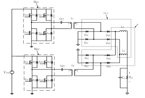
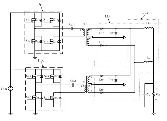
[0020] Such as figure 2 As shown, as the second embodiment of the present invention, the main circuit of the combined converter includes a full-bridge module circuit for full-wave cross-rectification on the secondary sides of two sets of transformers. A full bridge circuit Hp1, a DC blocking capacitor Cp1, a high frequency isolation transformer T1 with a center tap on the secondary side, and a full wave rectifier circuit LL1 constitute one of the circuit modules. The full-bridge circuit Hp2, the DC blocking capacitor Cp2, the high-frequency isolation transformer T2 with the center tap of the secondary sideband, and the full-wave rectifier circuit LL2 form another circuit module. Since the internal structures of the two circuit modules are the same, for the convenience of explanation, only the internal structure of one of the circuit modules will be described below.

[0021] The full bridge circuit Hp1 is connected to the primary side of the transformer T1. The switch tubes ...


PUM


Abstract

The invention discloses an intersected rectification input-parallel and output-parallel combined converter. A main circuit of the combined converter comprises two isolation bridge-type module circuits of which the rectification outputs are connected together in an intersection manner; each bridge-type module circuit consists of a half bridge circuit or a full bridge circuit with a blocking capacitor, a high-frequency transformer, a rectification circuit and an output filter inductor; the half bridge or full bridge circuit is connected with the original edge of the transformer; the rectification circuit is connected with the auxiliary edge of the transformer; and the rectification outputs are connected with the two output filter inductors in the intersection manner. The input ends of the bridge-type circuits are connected in parallel with each other, and the output ends of the output filter circuits are connected in parallel with each other. By the intersection rectification circuit, the inconsistent rectification output voltages caused by inconsistent circuit parameters can be counteracted, so that natural current sharing of the two output filter inductors can be realized, and input natural current sharing of the two bridge-type circuits can be realized simultaneously; a current-sharing control ring is not needed to be arranged, and the current of the bridge-type circuits is not needed to be sampled, so the control step is simplified greatly, the power density and the reliability of the combined converter are improved, and the cost is reduced.

Description

technical field [0001] The invention belongs to the technical field of power electronics, in particular to an input-parallel-output-parallel combination converter for cross rectification. Background technique [0002] As the power level increases, the volume of the magnetic components of the converter will also increase, and the magnetic loss and the current stress of the switch tube will also increase accordingly, which limits the efficiency and power density of the converter. Connecting two or more converters in parallel at the input and output ends can reduce the power level of a single converter, thereby ensuring that a single converter can work at a higher switching frequency, which is conducive to improving power density. In addition, each converter is usually interleaved in parallel to reduce the input and output current ripple, thereby reducing the size of the input and output filter capacitors. In view of the above advantages, the input-parallel-output parallel com...

Claims


Application Information

Patent Timeline
Patent Type & Authority Applications(China)
IPC IPC(8): H02M3/335
Inventor 石健将罗劼程娟
Owner ZHEJIANG UNIV
Why Eureka
Try Eureka