Methods for decoder-side motion vector derivation

A technology of motion vector and end motion, applied in the field of data encoding/decoding

Inactive Publication Date: 2011-07-20
MEDIATEK INC
View PDF3 Cites 21 Cited by
  • Summary
  • Abstract
  • Description
  • Claims
  • Application Information

AI Technical Summary

Problems solved by technology

For example, the templates used in the TM full search mechanism are limited to inverted L-shaped templates with a fixed template size, almost all supported MB types require flags encoded in the bitstr

Method used


Image

  • Methods for decoder-side motion vector derivation
  • Methods for decoder-side motion vector derivation
  • Methods for decoder-side motion vector derivation

Examples


Embodiment Construction

[0033] Certain terms are used in the description and claims to refer to particular elements. Those skilled in the art should understand that hardware manufacturers may use different terms to refer to the same component. The specification and claims do not use the difference in name as a way to distinguish components, but use the difference in function of components as a criterion for distinguishing. "Includes" mentioned throughout the specification and claims is an open term, so it should be interpreted as "including but not limited to". In addition, the term "coupled" herein includes any direct and indirect means of electrical connection. Therefore, if it is described that the first device is coupled to the second device, it means that the first device may be directly electrically connected to the second device, or indirectly electrically connected to the second device through other devices or connection means.

[0034] The present invention provides an example of DMVD desi...


PUM


Abstract

An exemplary method for decoder-side motion vector derivation (DMVD) includes: checking a block size of a current block to be encoded and accordingly generating a checking result; and utilizing a DMVD module to refer to the checking result to control conveyance of first DMVD control information which is utilized for indicating whether a DMVD coding operation is employed to encode the current block. When the checking result indicates a predetermined criterion is satisfied, the first DMVD control information is sent in a bitstream; otherwise, the first DMVD control information is not sent.

Description

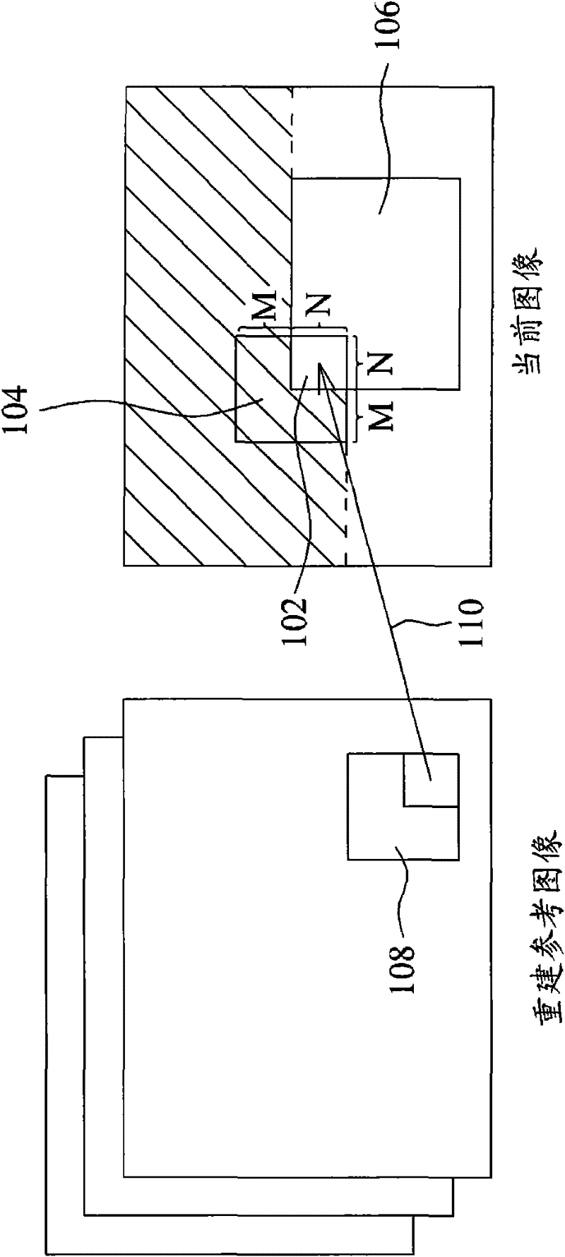
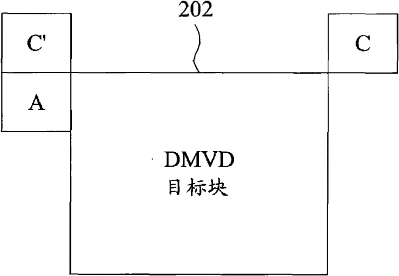
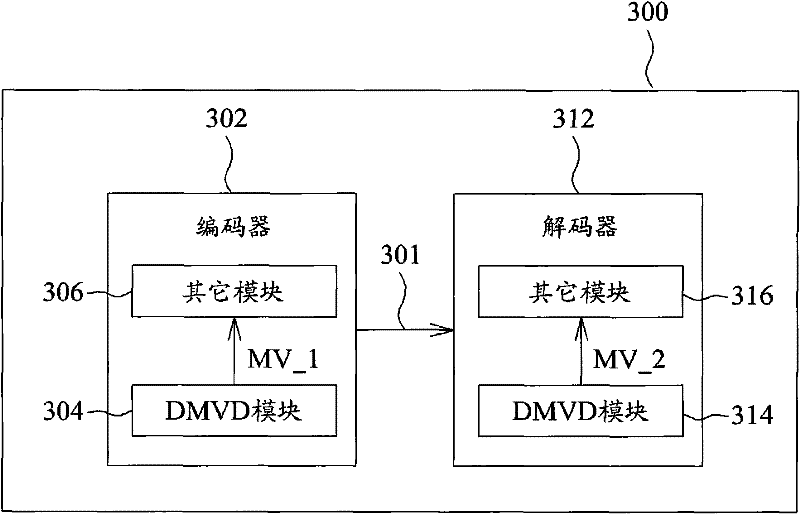
technical field [0001] The present invention relates to a data encoding / decoding method, and in particular to a decoder-side motion vector derivation (Decoder-side Motion Vector Derivation, hereinafter referred to as DMVD) method. Background technique [0002] In video coding, the temporal and spatial correlations found in image sequences can be exploited to reduce bitrate / enhance coding efficiency. Generally speaking, motion compensated inter-frame prediction (motioncompensated inter-frame prediction) largely affects the final compression efficiency. Motion information such as motion vector (MV) data and reference image index is obtained at the encoder and encoded in the bitstream, so the decoder can simply perform motion compensation prediction based on the decoded motion information. However, encoding of motion information requires a high bit rate. Therefore, a DMVD mechanism is proposed. [0003] A template matching (Template Matching, TM) algorithm may be used at the...

Claims


Application Information

Patent Timeline
IPC IPC(8): H04N7/26H04N7/32H04N19/56
Inventor 黄毓文蔡玉宝傅智铭雷少民
Owner MEDIATEK INC
Why Eureka
Try Eureka