A DC current breaker

A current and capacitor technology, applied in the field of DC breaker, can solve problems such as current zero crossing

Active Publication Date: 2011-07-20
HITACHI ENERGY SWITZERLAND AG
View PDF2 Cites 14 Cited by
  • Summary
  • Abstract
  • Description
  • Claims
  • Application Information

AI Technical Summary

Problems solved by technology

This active resonant circuit makes it possible to obtain the current zero crossing necessary to interrupt a DC current of more than 2500 amps (say in the order of 4000 amps) flowing through the interrupter

Method used


Image

  • A DC current breaker
  • A DC current breaker
  • A DC current breaker

Examples


Embodiment Construction

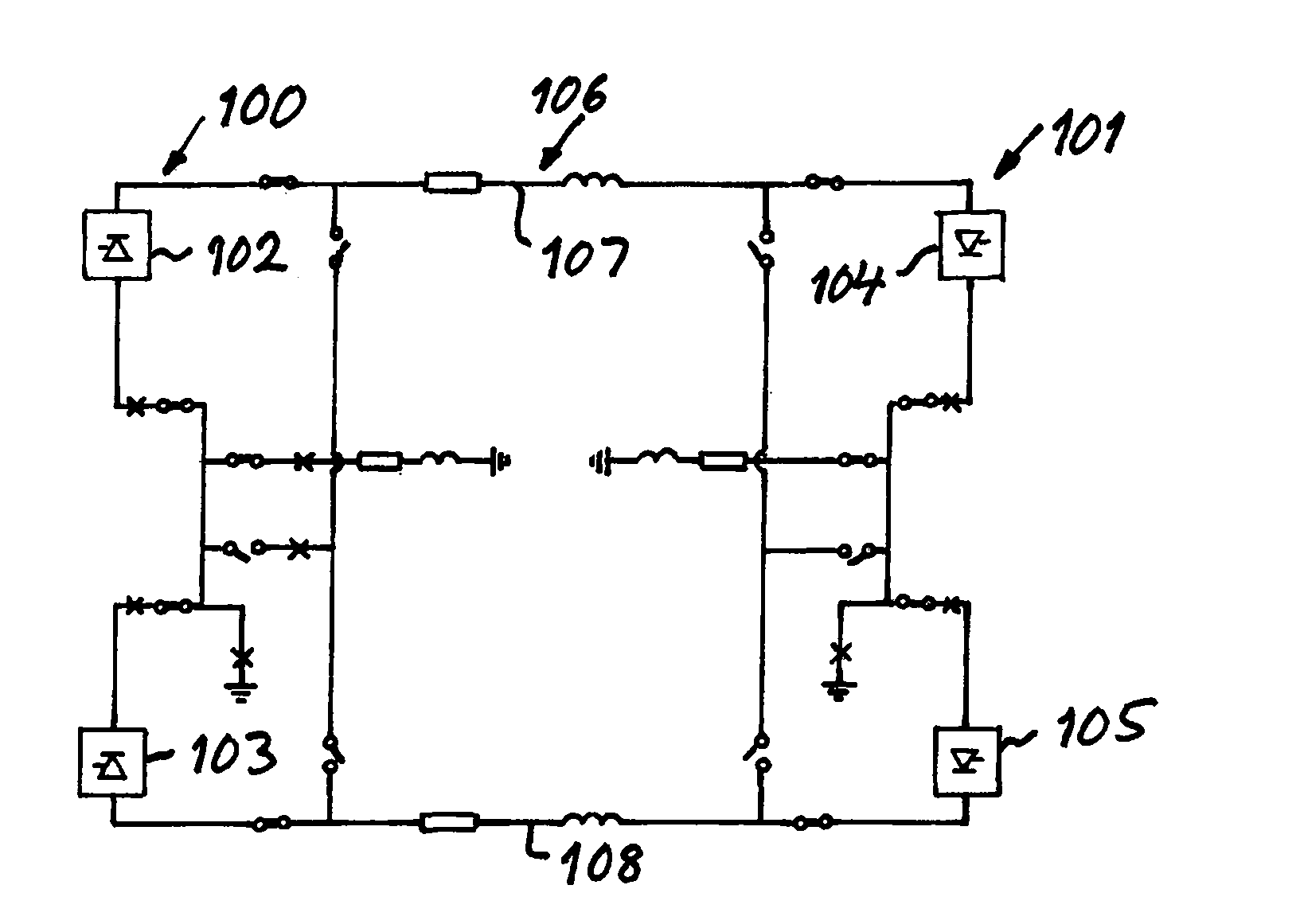
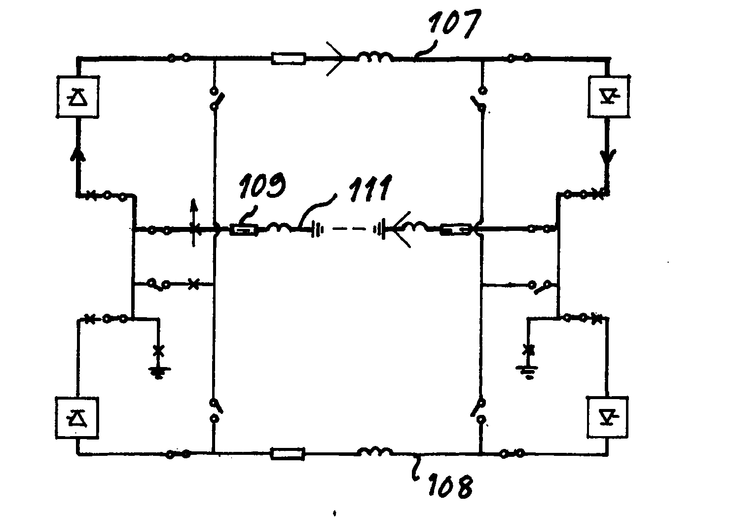
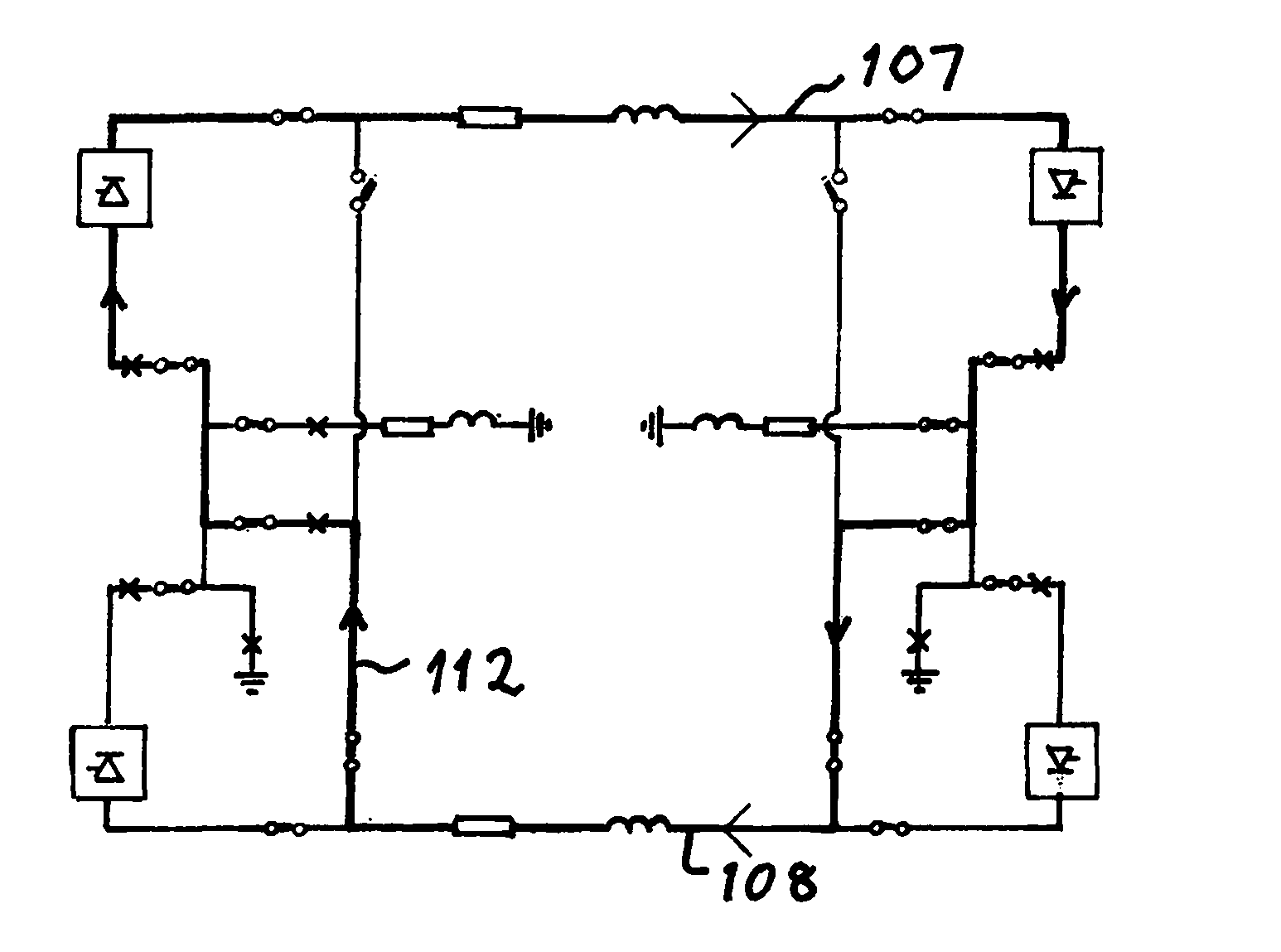
[0035] Figure 5 A device according to a first embodiment of the invention is shown, the device comprising a single interrupter 1 arranged in the first current path 8, the interrupter 1 having contacts 9, 10, the contacts 9, 10 The interrupters are movable relative to each other from a closed position to an open position to interrupt current flow through the interrupters. The device also has a resonant circuit 2 connected in parallel with the interrupter, comprising a capacitor 3 and an inductance 4 formed only by the self-inductance of the conductor 11 used to connect the capacitor 3 in parallel with the interrupter. The series connection of capacitors and inductors is configured to generate an oscillating current which is superimposed on the DC current flowing through the interrupter to break at the zero crossing of the current flowing through the interrupter so that when the contacts 9, 10 are connected to each other Removal allows this current to be interrupted. The devi...


PUM


Abstract

A device for breaking DC currents exceeding 2500 A has a resonance circuit (2) connected in parallel with an interrupter (1) and a surge arrester (7) connected in parallel with the resonance circuit. The resonance circuit has a series connection of a capacitor (3) and an inductance (4). The specific value relationship of the capacitance in microfarad to the inductance in microhenry of the resonance circuit is not less than 1.

Description

technical field [0001] The present invention relates to an apparatus configured to interrupt a DC current exceeding 2500 Amperes flowing in a first current path and divert said DC current to an alternative second current path. Background technique [0002] The equipment includes: [0003] - at least one interrupter arranged in said first current path, said interrupter having contacts movable relative to each other from a closed position of said interrupter to an open position to interrupts the current flow through the interrupter, [0004] a resonant circuit connected in parallel with the interrupter, the resonant circuit comprising a capacitor and an inductor connected in series and configured to generate an oscillating current which is superimposed on the DC current to create a zero crossing of the current through the interrupter, thereby enabling the current to be interrupted when the contacts move away from each other, and [0005] a surge arrester connected in parall...

Claims


Application Information

Patent Timeline
Patent Type & Authority Applications(China)
IPC IPC(8): H01H33/59
CPCH01H33/596Y02E60/60
Inventor 厄本·阿斯特罗姆拉尔斯·利耶斯特兰德维克托·莱斯卡勒芒努斯·贝克曼
Owner HITACHI ENERGY SWITZERLAND AG
Why Eureka
Try Eureka