Waste heat recovery components

A waste heat recovery and component technology, applied in heat exchangers, indirect heat exchangers, heat exchanger types, etc., can solve problems such as the reduction of waste heat recovery effect, and achieve the effect of improving efficiency, improving heat insulation effect, and being easy to pick and place.

Active Publication Date: 2020-08-25
重庆岩昱节能科技有限公司
View PDF11 Cites 0 Cited by
  • Summary
  • Abstract
  • Description
  • Claims
  • Application Information

AI Technical Summary

Problems solved by technology

[0005] The invention provides a waste heat recovery component, which solves the problem in the prior art that the recovery effect of waste heat is greatly reduced due to the continuous overflow of hot air from the top of the recovery component

Method used


Image

  • Waste heat recovery components
  • Waste heat recovery components
  • Waste heat recovery components

Examples


Embodiment 1

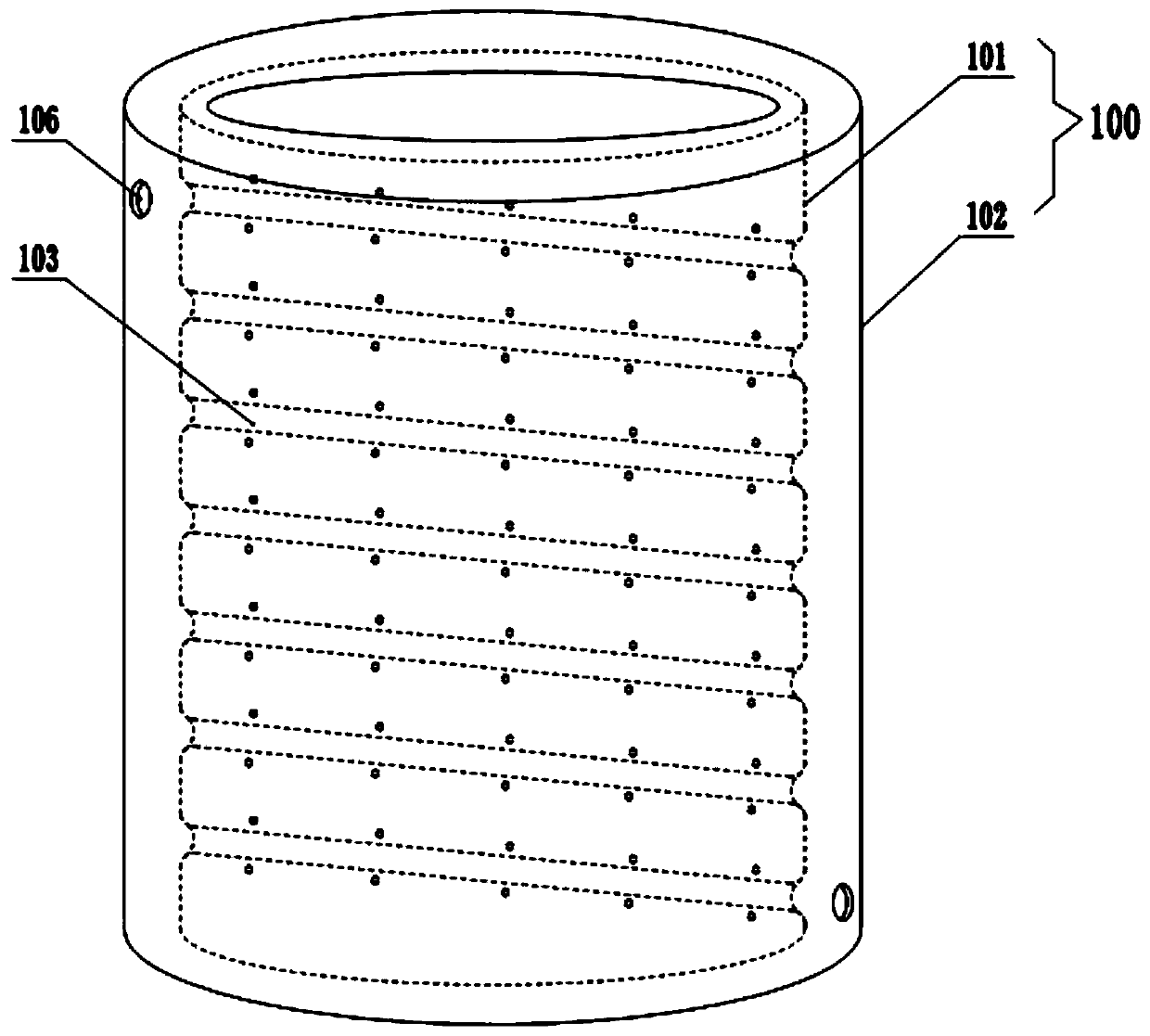
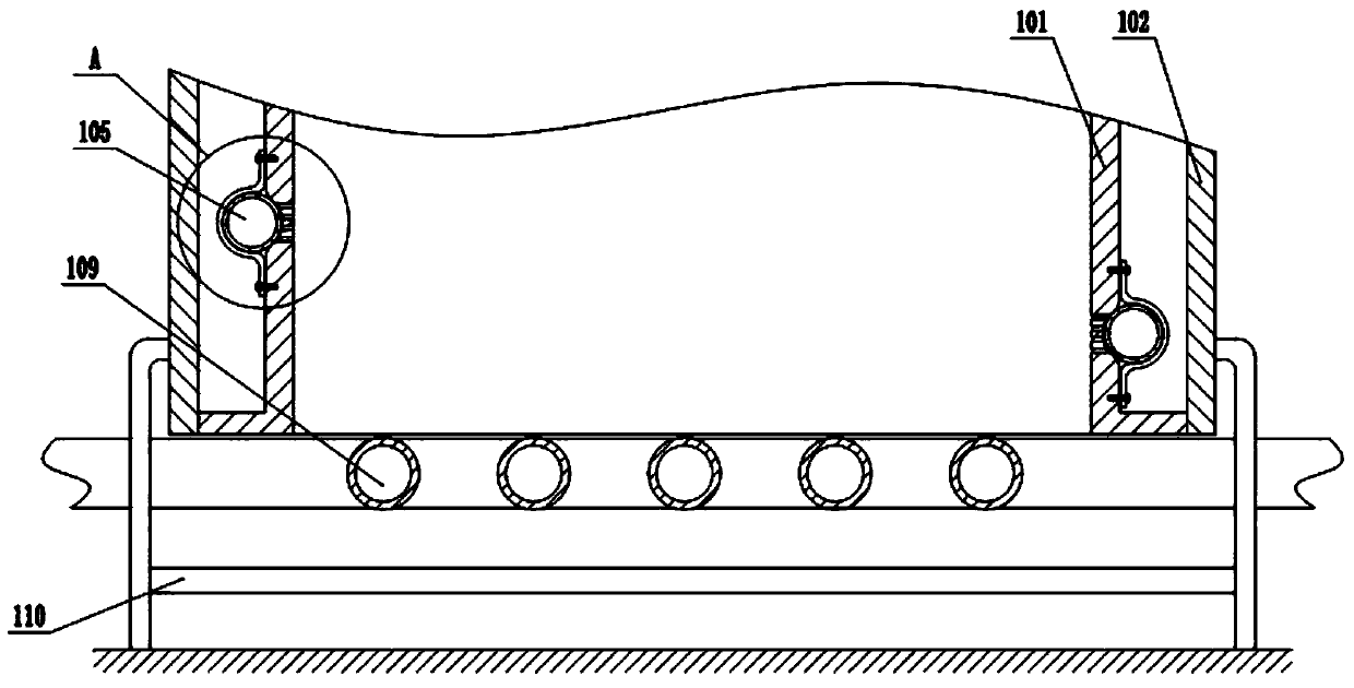
[0036] Embodiment 1 is basically as attached figure 1 and figure 2 shown:

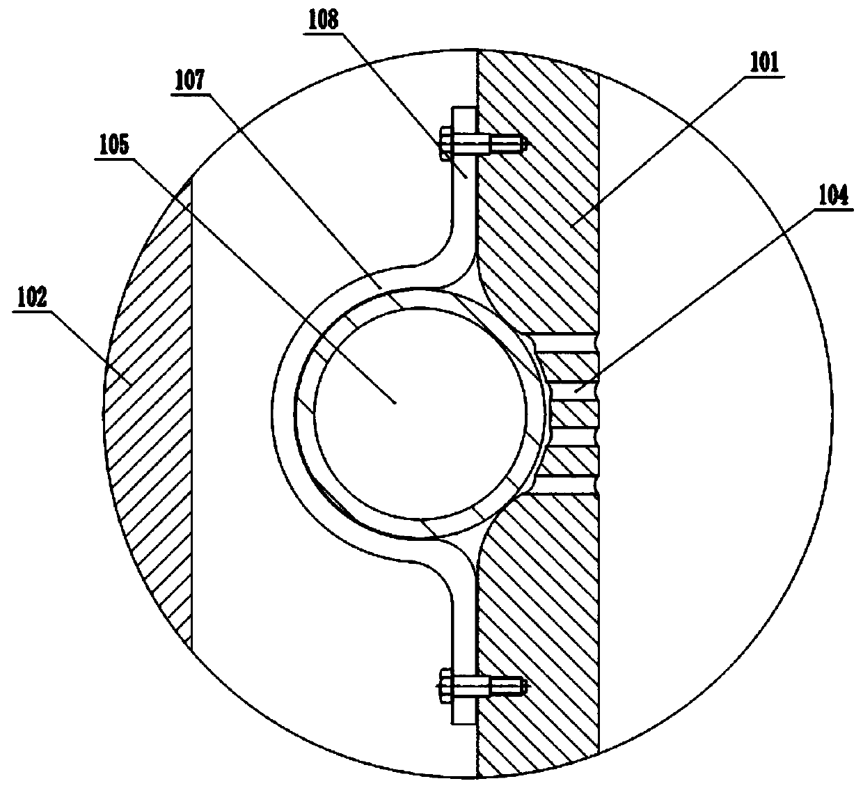
[0037] The waste heat recovery assembly includes a frame on which a vertically arranged heat-absorbing cylinder 100 is fixed. The heat-absorbing cylinder 100 is a sandwich structure, and specifically includes an inner cylinder 101 and an outer cylinder 102, and the inner cylinder 101 and the outer cylinder 102 are fixedly arranged , and a channel with closed upper and lower ends is formed between the inner and outer cylinders 102, a spiral groove 103 is opened on the outer wall of the inner cylinder 101, and the cross-section of the groove 103 is semicircular, such as image 3 , the inner wall of the inner cylinder 101 is provided with a plurality of heat dissipation holes 104 corresponding to the positions of the grooves 103 and communicated with each other, and the heat dissipation holes 104 are through holes, and the heat absorption pipes for the circulation of the heat exchange medium are clamped...

Embodiment 2

[0046] The difference between the second embodiment and the first embodiment is:

[0047] like Figure 5 As shown, a plurality of heat conducting units are evenly distributed along the protrusions 201 at the bottom of the top cover 200, and the heat conducting units are used to disperse the heat from the bottom of the top cover 200 to the heat absorption pipe 105, wherein the heat conducting units include the heat conducting plate 300 and the drive A drive mechanism for the heat-conducting plate 300 to swing back and forth around the horizontal axis. The heat-conducting plate 300 is located between the protrusion 201 and the inner cylinder 101 . In this embodiment, the drive mechanism includes a deceleration motor 301 and a guide rod 302 , and the deceleration motor 301 is fixed on the top cover 200 The top cover 200 is provided with a shaft hole for the output shaft of the reduction motor 301 to pass through, an incomplete gear 304 located under the top cover 200 is coaxially...


PUM


Abstract

The invention relates to the technical field of cooling industrial equipment and particularly discloses a waste heat recovery assembly which comprises a vertically arranged heat absorption cylinder, wherein the heat absorption cylinder comprises an inner cylinder and an outer cylinder; a passage allowing a heat exchanging medium to circulate is formed between the inner cylinder and the outer cylinder; a top cover covering the heat absorption cylinder is arranged at the top of the heat absorption cylinder; and an inverted tapered bulge is arranged in the bottom center of the top cover. With adoption of the technical scheme, the problem in the prior art that hot airflow continuously overflows out of the top of the recovery assembly to greatly lower the waste heat recovery effect is solved.

Description

technical field [0001] The invention relates to the technical field of cooling industrial equipment, in particular to a waste heat recovery component. Background technique [0002] Waste heat refers to the unused thermal energy generated by various thermal energy conversion equipment, energy-consuming equipment, chemical reaction equipment and high-temperature workpieces in the production process. There is a large amount of waste heat that needs to be recycled in industrial fields such as textile printing and dyeing, electroplating processing, chemical pharmacy, printing drying, coal slime drying, casting, and electrolytic aluminum production. If this part of energy can be fully utilized through recovery, industrial energy loss will be greatly reduced, and waste heat recovery and utilization is an important way to improve economy and save fuel. [0003] Based on the above problems, our company has developed a waste heat recovery cycle system, which includes a recovery compo...

Claims


Application Information

Patent Timeline
Patent Type & Authority Patents(China)
IPC IPC(8): F28D21/00F28F9/00
CPCF28D21/0001F28F9/001
Inventor 杨帆易启堂
Owner 重庆岩昱节能科技有限公司
Why Eureka
Try Eureka