Passive degasser

A passive degasser and main body technology, applied in liquid degassing, chemical instruments and methods, sampling devices, etc., can solve the problems of low degassing efficiency, poor degree of mud fragmentation, and affecting degassing efficiency

Active Publication Date: 2011-07-27
天津港保税区鑫利达石油技术发展有限公司
View PDF6 Cites 4 Cited by
  • Summary
  • Abstract
  • Description
  • Claims
  • Application Information

AI Technical Summary

Problems solved by technology

[0005] The industry generally believes that the degasser has generally experienced the first generation of degasser: that is, a square metal box is processed into a concave shape at the bottom, and the middle lead-out pipeline is connected to the suction pump. This device floats on the mud page and generally has no power source. , which belongs to a float type degasser, and its degassing efficiency is low
The second-generation degasser is an electric degasser. The motor drives the stirring rod to stir in the degassing barrel. The purpose is to break up the mud and separate the gas in the mud, and then pump the gas to the mud logging room through the sample gas pump. , the degassing efficiency has been improved, but due to the great influence of the change of the liquid level of the mud tank, the mud flow is unstable, and the slurry inlet of the degassing device does not have

Method used


Image

  • Passive degasser
  • Passive degasser
  • Passive degasser

Examples


Embodiment Construction

[0098] Below in conjunction with preferred embodiments, the specific implementation, features and effects provided by the present invention are described in detail as follows; for the purpose of simplicity and clarity, the description of known technologies is appropriately omitted below to avoid unnecessary details Affect the description of this technical solution.

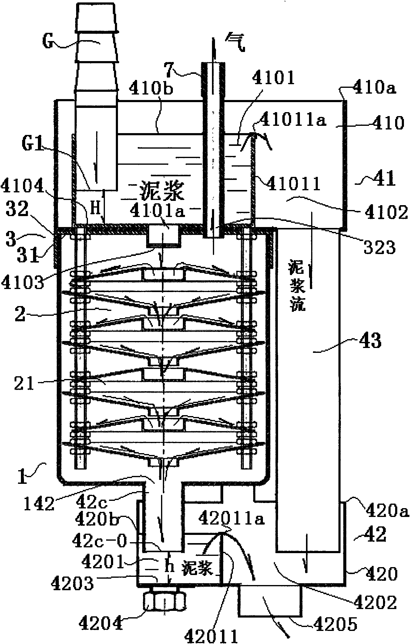
[0099] see Figure 1-4 As shown, a passive degasser includes a tank body 1, the tank body has a mud inlet and a mud outlet 142, the upper part of the tank body is the mud inlet end, and the lower part of the tank body is the mud outlet end, wherein,

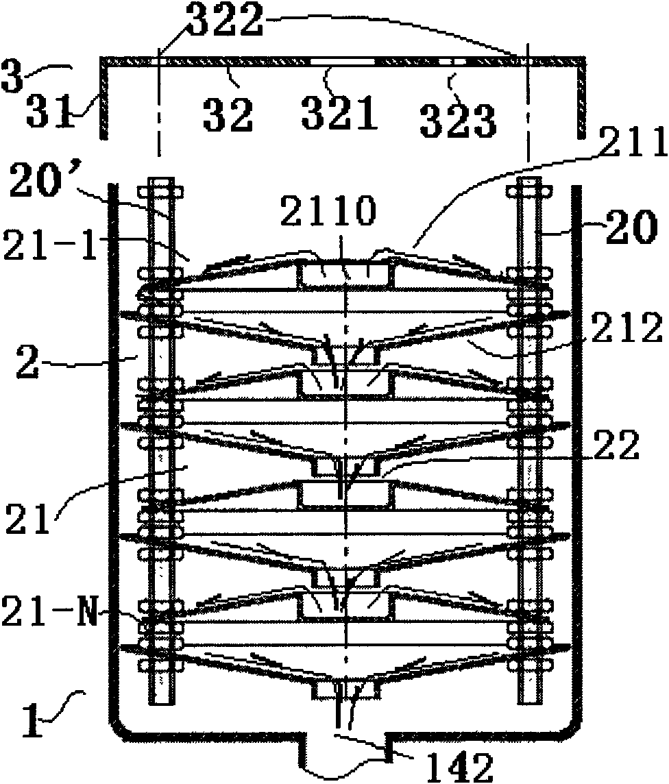
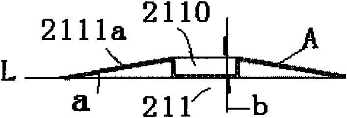
[0100] see figure 1 A mud treatment body 2 is installed in the tank body 1, and the mud treatment body is used to diffuse the mud as much as possible, so that the gas is separated from the mud;

[0101] The upper part of the tank body is provided with an assembly end cap 3, which is composed of an end cap airtight seam 31 and an assembly end face 32. On the one ha...


PUM


Abstract

The invention provides a passive degasser relating to a device for on line detaching gas in slurry lifted during oil exploration drilling, which is particularly suitable for the passive degasser. The passive degasser comprises a pot body, wherein the pot body is provided with a slurry inlet and a slurry outlet; the upper part of the pot body is the slurry inlet end; the lower end of the pot body is the slurry outlet end; and a slurry treatment body is arranged in the pot body. In the invention, the slurry treatment body is arranged to disperse and degas the slurry to be treated, and under a circumstance of having no power source drive, the slurry can be further diffused, that is fully dispersed, therefore, the degassing efficiency is effectively increased; and an airtight construction is arranged on the pot body to ensure that the slurry can be under an airtight condition in the whole degassing process of the degasser and all the gases collected by a sample air pump are the gases detached in treating the slurry in the pot body so as to provide guarantee for the accuracy of sample gas collecting data and for detecting the true gas content of a stratum.

Description

technical field [0001] The invention belongs to equipment for comprehensive mud logging and gas logging, and relates to a device for on-line degassing of mud proposed in oil exploration and drilling, and is especially suitable for a passive degasser, that is, the degasser does not need to be driven by a power source. Background technique [0002] The degassing device is an important part of the comprehensive mud logging and gas logging equipment. It shoulders the important task of whether the sample gas can better represent the real gas content of the formation, and directly affects the accuracy of oil and gas field evaluation. [0003] The industry's research on its improvement has never stopped. [0004] For example, the published Chinese patent "200410059804.5 A system for removing gas from mud and analyzing gas contained in mud" describes a physical and chemical analysis device for gas extracted online from mud proposed in oil exploration drilling, mentioning Degassing ...

Claims


Application Information

Patent Timeline
IPC IPC(8): B01D19/00G01N1/22
Inventor 李明利李明春
Owner 天津港保税区鑫利达石油技术发展有限公司
Why Eureka
Try Eureka