
Cutter joint assembly and processing system

A processing system and tool joint technology, which is applied in processing special circuits, metal processing equipment, electric processing equipment, etc., can solve the problems of time-consuming preparation work, low efficiency of tool replacement, and difficulty in setting up electric processing functions in the processing system.

Active Publication Date: 2011-07-27
GENERAL ELECTRIC CO
View PDF6 Cites 13 Cited by
  • Summary
  • Abstract
  • Description
  • Claims
  • Application Information

AI Technical Summary

Problems solved by technology

[0004] However, in some existing technologies, it is difficult to set the electric machining function for the machining system
In addition, for some existing machining systems with electric machining functions, the preparation work before electric machining is relatively time-consuming, and the efficiency of tool replacement is not high

Method used


Image

  • Cutter joint assembly and processing system
  • Cutter joint assembly and processing system
  • Cutter joint assembly and processing system

Examples


Embodiment Construction

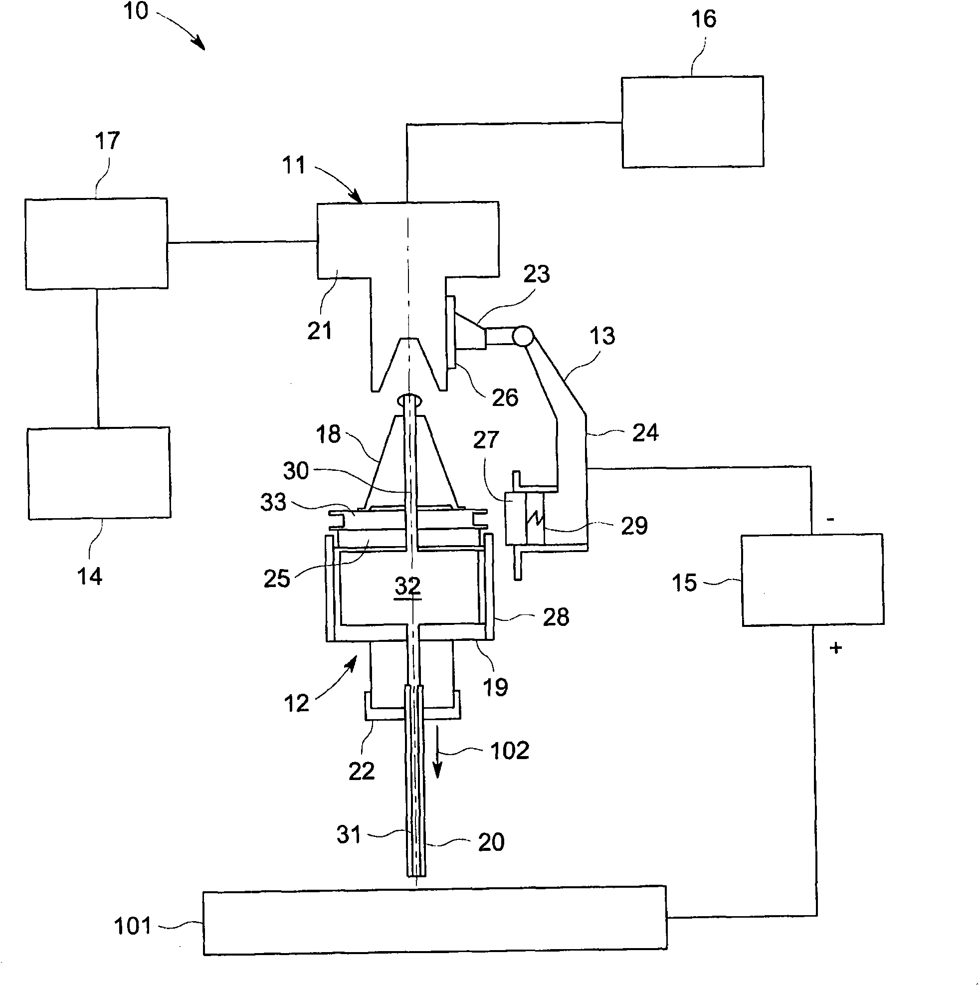
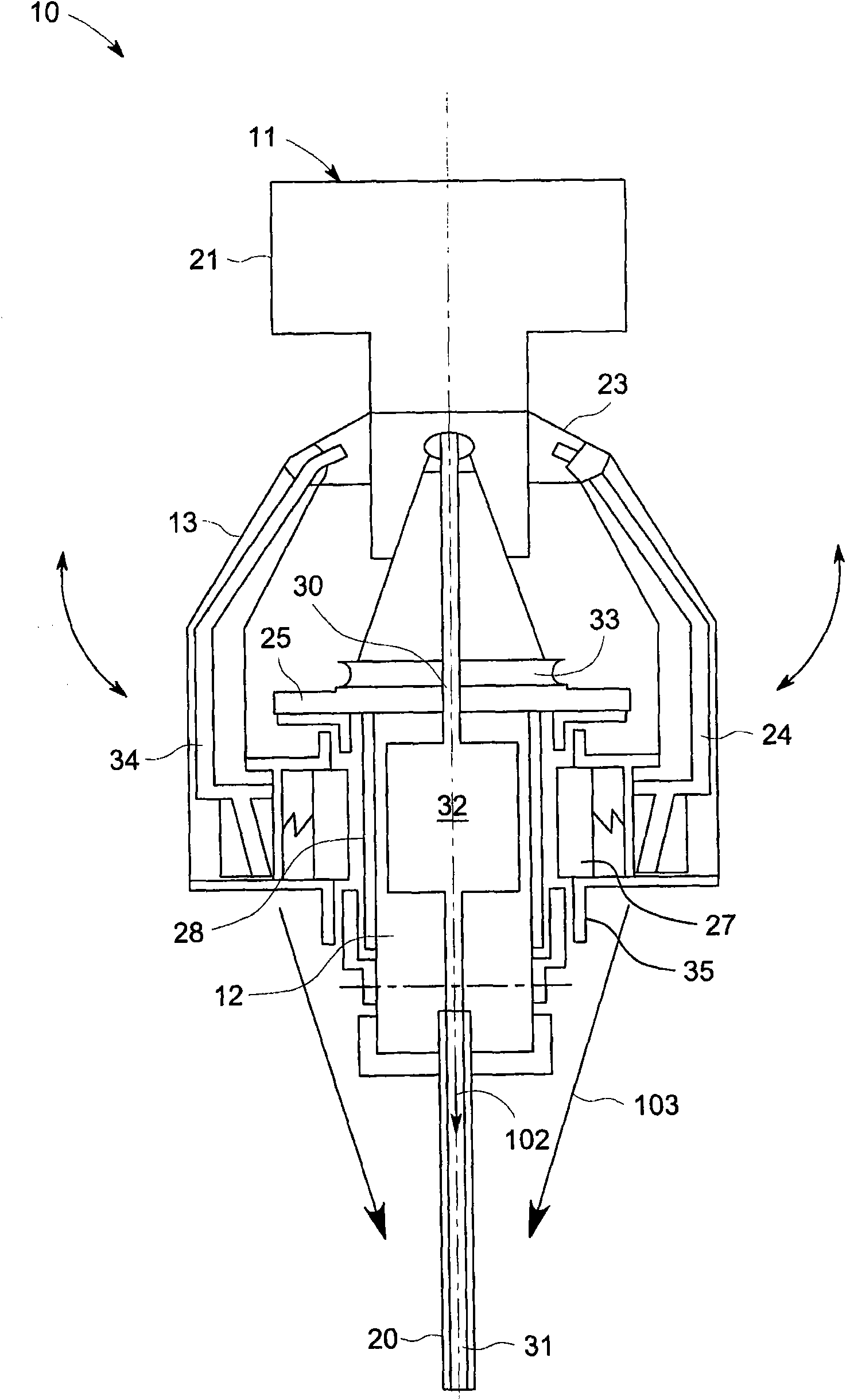
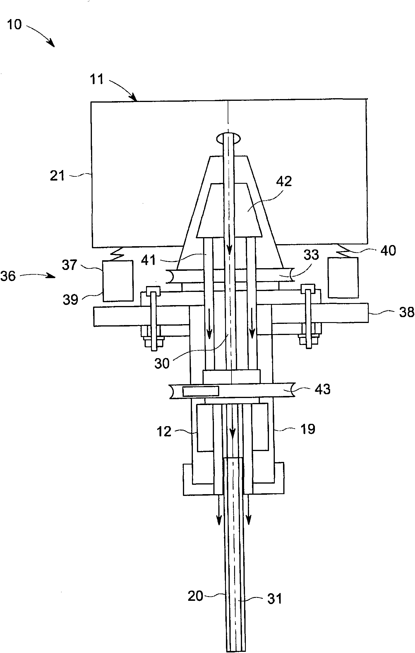
[0014] figure 1 A schematic diagram of one embodiment of a machining system 10 for machining a workpiece 101 is shown. In some embodiments, the processing system 10 includes computer numerical control (Computer Numerical Controlled, CNC) machine tools or machining centers (Machining Centers), which can automatically process the workpiece 101 with one or more tools according to a preset control program. The one or more tools may be stored in a tool magazine of the machining system. In some applications, the machining system 10 may not be provided with a tool magazine.

[0015] Such as figure 1 As shown, the machining system 10 includes a machine tool 11 , a tool joint assembly (not labeled), a tool transfer device 14 , a power source 15 , a machining fluid source 16 and a controller 17 . Wherein, the tool joint assembly includes an adapter 13 and a tool holding device 12 provided with a tool 20 . figure 1 The illustrated examples do not limit the invention. exist Figu...


PUM


Abstract

The invention discloses a cutter joint assembly and a processing system. The processing system for electrically processing a workpiece comprises a machine tool, an electrode, a cutter holding device and an adapter. The machine tool comprises a main shaft. The electrode can be used for electrical processing. The cutter holding device is arranged on the main shaft of the machine tool and conductively holds the electrode. The adapter is conductively contacted with the cutter holding device. The processing system further comprises a power supply and a processing liquid source. The power supply can be connected with the adapter and the workpiece so that the workpiece and the electrode have opposite polarities. The processing liquid source can provide processing liquid passing through the place between the electrode and the workpiece. Moreover, the invention also relates to the cutter joint assembly.

Description

technical field [0001] The invention relates to a tool joint assembly and a processing system provided with the tool joint assembly, in particular to a tool joint assembly for electric machining and a processing system provided with the tool joint assembly. Background technique [0002] Machining systems, such as Computer Numerical Controlled (CNC) machine tools or Machining Centers, have been widely used to process workpieces. Due to non-contact processing, high efficiency and low tool cost, more and more processing systems are equipped with electric machining functions to process workpieces, such as processing workpieces with high hardness. [0003] Generally, in electrical machining, such as Electro Discharge Machining (EDM), Electrochemical Machining (ECM) and Electrochemical Discharging Machining (ECDM), an electrode as a cathode is placed above a conductive workpiece , the current is passed between the electrode and the workpiece to remove the workpiece material to ma...

Claims


Application Information

Patent Timeline
Patent Type & Authority Applications(China)
IPC IPC(8): B23H7/00B23H7/26
CPCB23H7/20B23H3/10B23H7/36B23H9/14B23H3/02
Inventor 李红涛袁人炜罗元丰陈晓宾魏斌史蒂文·R·哈亚西
Owner GENERAL ELECTRIC CO
Learn More