Tailstock type vertical take-off and landing unmanned aerial vehicle

An unmanned aerial vehicle, vertical take-off and landing technology, applied in the field of unmanned aerial vehicles, can solve problems such as flight restrictions and flight dangers, and achieve the effects of simplified power, simple structure, and flexible control

Inactive Publication Date: 2011-07-27
SHANGHAI UNIV
View PDF1 Cites 38 Cited by
  • Summary
  • Abstract
  • Description
  • Claims
  • Application Information

AI Technical Summary

Problems solved by technology

In the early days, there was Boeing's Heliwing. Heliwing needs to reach a certain height and speed before it can turn from vertical to horizontal flight, so its flight is subject to some restrictions; and the transition from vertical to horizontal flight will also be accompanied by a "stall roll" action. This poses a certain danger to flying

Method used


Image

  • Tailstock type vertical take-off and landing unmanned aerial vehicle
  • Tailstock type vertical take-off and landing unmanned aerial vehicle
  • Tailstock type vertical take-off and landing unmanned aerial vehicle

Examples


Embodiment 1

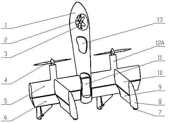
[0015] Embodiment one: see figure 1 , a tail-sitting vertical take-off and landing unmanned aerial vehicle, comprising a fuselage 1, wings 5 ​​and a vertical tail 10, a support frame 2 is arranged at the head of the fuselage 1, and a pitch fan 3 is installed on the support frame 2, The middle part of the fuselage 1 has a cabin 13, and a built-in battery 11 in the tail; the wing 5 is connected to the tail of the fuselage 1, and four vertical tail fins 10 are symmetrically distributed up and down, left and right, and the rear of the wing 5 A roll and pitch control rudder surface 6 is installed at the top; two mutually independent motors 12A are fixed at the junction of the wing 5 and the vertical tail 10, and each of the two motors 12A drives a propeller 4; the four vertical tails 10 rear portions are respectively equipped with a yaw control rudder surface 9 and a landing gear 8, and each landing gear 8 rear portion is equipped with a universal roller 7; the pitch fan 3 is drive...

Embodiment 2

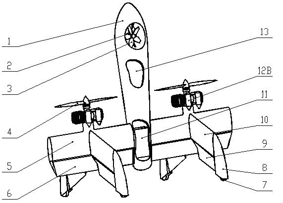
[0017] Embodiment two: see figure 2 , a tail-sitting vertical take-off and landing unmanned aerial vehicle, comprising a fuselage 1, wings 5 ​​and a vertical tail 10, a support frame 2 is arranged at the head of the fuselage 1, and a pitch fan 3 is installed on the support frame 2, The middle part of the fuselage 1 has a cabin 13, and a built-in battery 11 in the tail; the wing 5 is connected to the tail of the fuselage 1, and four vertical tail fins 10 are symmetrically distributed up and down, left and right, and the rear of the wing 5 A roll and pitch control rudder surface 6 is installed at the top; two mutually independent motors 12B are fixed at the junction of the wing 5 and the vertical tail 10, and each of the two motors 12B drives a propeller 4; the four vertical tails 10 rear portions are respectively equipped with a yaw control rudder surface 9 and a landing gear 8, and each landing gear 8 rear portion is equipped with a universal roller 7; the pitch fan 3 is driv...


PUM


Abstract

The invention discloses a tailstock type vertical take-off and landing unmanned aerial vehicle. A pitching fan is mounted at the head of a body; the tail of the body is connected with wings; four vertical tails are distributed on the wings in a vertically and bilaterally symmetric manner; an off-course rudder and a landing gear are mounted behind the vertical tails; and two mutually independent propellers are fixed at the junction of the wings and the vertical tails. According to the invention, as the tailstock type fixed-wing vertical take-off and landing technology is adopted, the unmanned aerial vehicle not only can vertically take off and land and hover as a helicopter, but also can cruise at a high speed as a fixed-wing aircraft; and the structure is simple, the power is simplified, and the manipulation is flexible. Due to the pitching fan at the head of the body, the aerial vehicle can fly more actively; and particularly in transitional flying from a vertical state to a horizontal state or from a horizontal state to a vertical state, the advantages are more obvious, and the vertical-to-horizontal conversion can be finished only by rising a short distance or in a hovering state.

Description

technical field [0001] The invention relates to an unmanned aerial vehicle, in particular to a tail-sitting vertical take-off and landing unmanned aerial vehicle. Background technique [0002] With the vigorous development of computer technology, communication technology and electronic technology, research on unmanned aerial vehicles has gradually formed an upsurge in the world. Compared with helicopters, fixed-wing aircraft has the advantages of high flight efficiency, fast flight speed, long flight distance, simple system structure, light weight, low cost and use fee, etc., but fixed-wing aircraft also has its own inevitable defects, that is, in Takeoff and landing require taxiing or use of special launch recovery devices. [0003] Vertical take-off and landing technology makes it possible for aircraft to combine the performance and advantages of helicopters and fixed wings. At present, the more successful vertical take-off and landing schemes mainly include: tilting rot...

Claims


Application Information

Patent Timeline
IPC IPC(8): B64C27/22
Inventor 程世富饶进军
Owner SHANGHAI UNIV
Why Eureka
Try Eureka