Temperature fuse module

A technology of top block and metal conductor, applied in the direction of thermal switch components, etc., can solve the problems of thermal protector being unable to withstand large current impact, long response time, etc., to achieve the effect of rapid power cut off, sensitive response, and prevention of fire and burning

Inactive Publication Date: 2015-12-16
THINKING ELECTRONIC IND CO LTD
View PDF6 Cites 4 Cited by
  • Summary
  • Abstract
  • Description
  • Claims
  • Application Information

AI Technical Summary

Problems solved by technology

[0002] The traditional thermal fuse is placed in a closed cavity with two parallel metal electrodes connected by a fusible alloy, and the package is designed to help the melting electrode. When the external temperature reaches a certain temperature range, it is easy to The molten alloy is melted and disconnected, the power supply is cut off, and the hidden danger of combustion caused by the continuous rise of the temperature of the protected component is avoided; however, the selection of the fusible alloy, the size of the solder joint control, the selection of the flux, and the design of the temperature sensing structure are affected by the thermal fuse in production. The influence of many factors such as temperature sensitivity and the speed of breaking the fusible alloy has a great influence, and the response time is very long
[0003] The existing shrapnel type thermal protector adopts the structural design of bimetallic sheet plus dynamic and static contacts. When the external temperature rises to a certain temperature range, the bimetallic sheet springs up and the dynamic and static contacts are effectively disconnected; when the external temperature drops When it reaches a certain temperature range, the bimetallic sheet springs back, and the movable and static contacts are reconnected, thereby realizing temperature control; but this kind of thermal protector cannot withstand the impact of large current

Method used


Image

  • Temperature fuse module
  • Temperature fuse module
  • Temperature fuse module

Examples


Embodiment 1

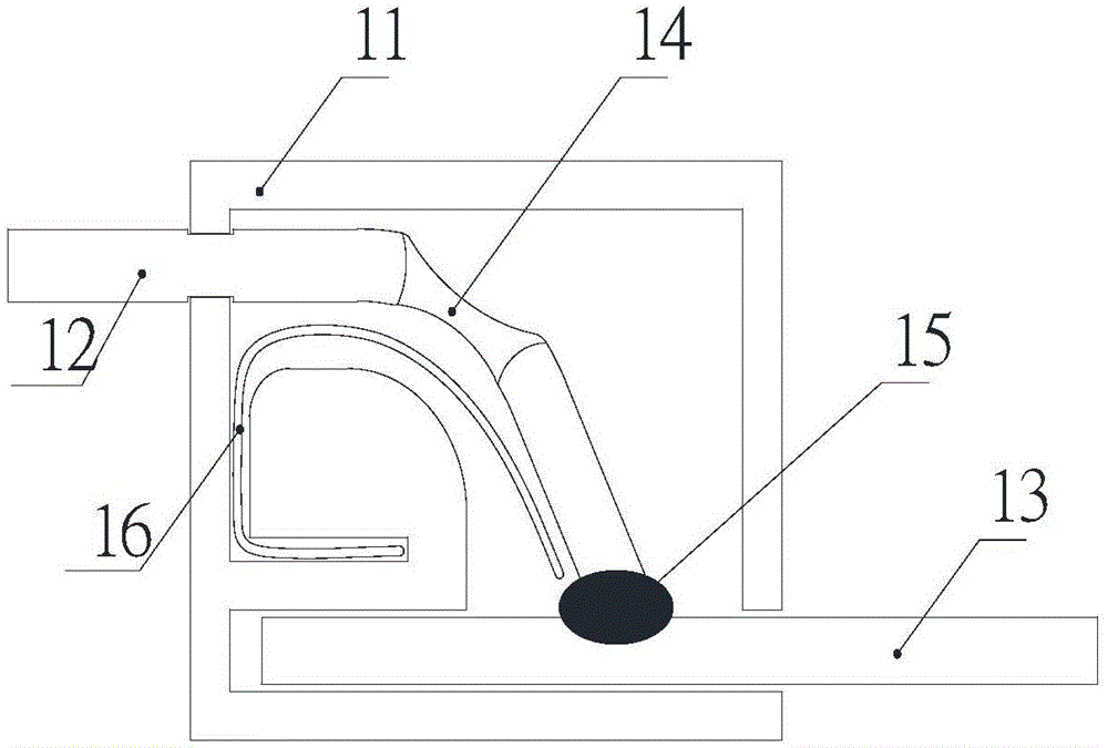
[0020] Such as figure 1 As shown, a thermal fuse module of the present invention includes an insulating housing 11, a first metal conductor 12, a second metal conductor 13 and an elastic structure 16, and a bending point 14 is provided on the first metal conductor 12, and the first The metal conductor 12 and the second metal conductor 13 are welded by the fusible alloy 15, and the first metal conductor 12 and the second metal conductor 13 respectively extend outside the insulating housing 11 to form the electrode end of the connecting circuit; the elastic structure 16 leans against the On the first metal conductor 12 , when the fusible alloy 15 is melted, the elastic structure 16 can effectively disconnect the first metal conductor 2 and the second metal conductor 3 .

Embodiment 2

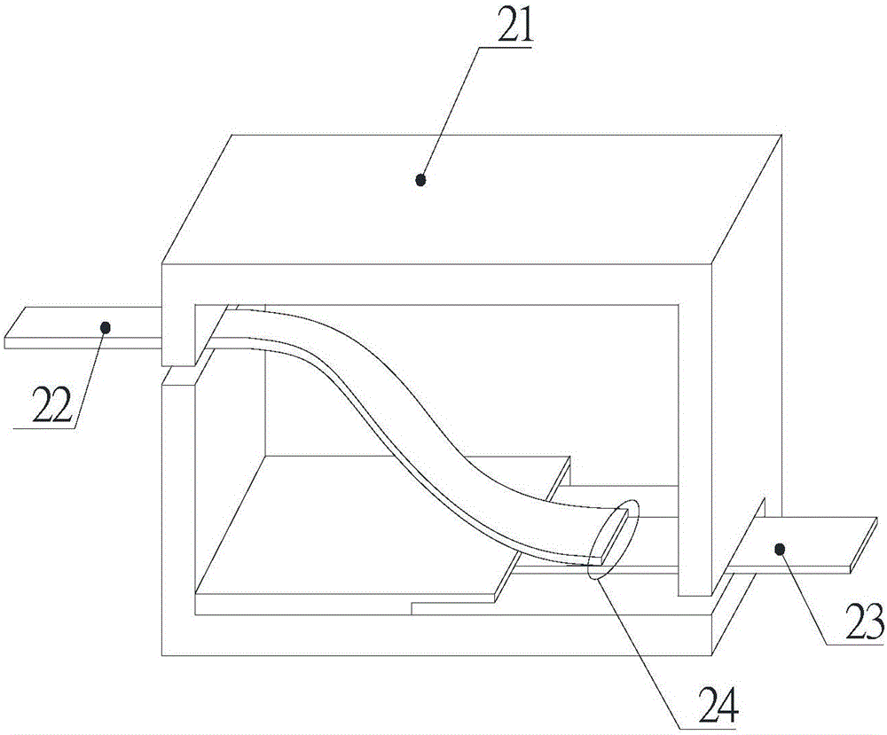
[0022] Such as figure 2 As shown, a thermal fuse module of the present invention includes an insulating housing 21, an elastic structure 22, a metal conductor 23, the elastic structure 22 and the metal conductor 23 are welded by a fusible alloy 24, the elastic structure 22 and the metal conductor 23 They respectively extend outside the insulating casing 21 to form electrode terminals connecting the circuit; when the fusible alloy 24 melts, the elastic structure 22 can be effectively disconnected from the metal conductor 23 .

Embodiment 3

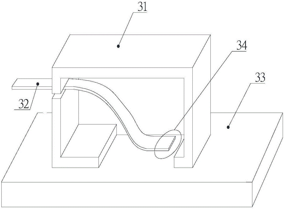
[0024] Such as image 3 As shown, a thermal fuse module of the present invention includes an insulating housing 31, an elastic structure 32, the elastic structure 32 is welded to an object 33 to be installed through a fusible alloy 34, and the elastic structure 32 extends outside the insulating housing 31. The electrode end of the connection circuit is formed; when the fusible alloy 34 is melted, the elastic structure 32 can be effectively disconnected from the object 33 to be installed.


PUM


Abstract

The invention relates to a temperature fuse module. The temperature fuse module comprises an insulation shell, wherein a first metal conductor is arranged in the insulation shell, one end of the first metal conductor extends out of the insulation shell and forms an electrode end of a connection circuit, the other end of the first metal conductor is connected with a second metal conductor through a fusible alloy or directly connected with an object to be installed, one end at which the first metal conductor and the second metal conductor or the object to be installed are connected is separated from the second metal conductor or the object to be installed after the fusible alloy is fused. Compared with the temperature fuse used in the current market, the temperature fuse module has the advantages that an elastic structure design is adopted, and functions of sensitive response, active and rapid power supply cut off and fire prevention are achieved; compared with the traditional temperature fuse and the traditional passively-heated fuse, the temperature fuse module has obvious advantages in feedback speed and high-current impact bearing; and the temperature fuse module can be applicable for and substitute the traditional temperature fuse and is suitably used for protecting various over-voltage circuits.

Description

technical field [0001] The invention relates to a temperature insurance module, in particular to a temperature insurance module with fast response speed and capable of withstanding large current impact. Background technique [0002] The traditional thermal cutoff adopts a closed cavity, which is placed with two parallel metal electrodes connected by a fusible alloy, and encapsulated with a design to help the melting electrode. When the external temperature reaches a certain temperature range, it is easy to The molten alloy is melted and disconnected, the power supply is cut off, and the hidden danger of combustion caused by the continuous rise of the temperature of the protected components is avoided; The influence of many factors such as temperature sensitivity and the speed of breaking the fusible alloy has a great influence, and the response time is very long. [0003] The existing shrapnel type thermal protector adopts the structural design of bimetallic sheet plus dyna...

Claims


Application Information

Patent Timeline
Patent Type & Authority Applications(China)
IPC IPC(8): H01H37/46
CPCH01H37/46
Inventor 韩纪念唐俊隋介衡黄任亨李晓乐
Owner THINKING ELECTRONIC IND CO LTD
Why Eureka
Try Eureka