Composite moving bed bio-film reactor

A technology of moving bed biofilm and reactor, which is applied in the field of compound moving bed biofilm reactor, can solve the problems such as unsatisfactory treatment effect, and achieve the effects of less floor space, large amount of loss prevention and long contact time

Inactive Publication Date: 2011-07-27
SHANDONG JIANZHU UNIV
View PDF6 Cites 24 Cited by
  • Summary
  • Abstract
  • Description
  • Claims
  • Application Information

AI Technical Summary

Problems solved by technology

[0004] The reactor body used in the traditional moving bed biofilm reactor is equipped with an inclined

Method used


Image

  • Composite moving bed bio-film reactor
  • Composite moving bed bio-film reactor

Examples


Embodiment Construction

[0037] In order to clearly illustrate the technical characteristics of this program, a specific implementation will be adopted below, combined with its

[0038] Accompanying drawing, this scheme is described.

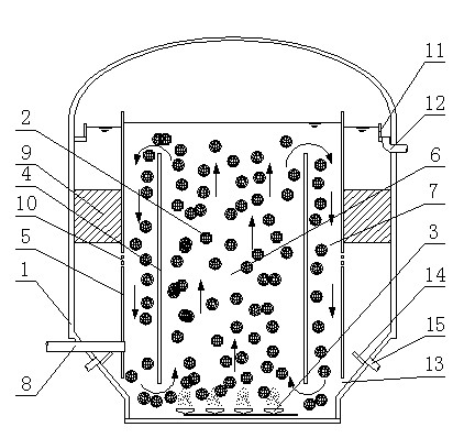
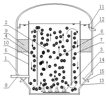
[0039] As shown in the accompanying drawings, the present invention is a composite moving bed biofilm reactor, which includes a reactor body 1 in which hollow ball fillers 2 are put in, and the inner bottom of the reactor body 1 is provided with a gas device 3, the reactor body 1 is also provided with two sets of inner cylinder 4 and outer cylinder 5, the upper and lower openings of the inner cylinder 4 and outer cylinder 5 are completely open, and the height of the inner cylinder 4 is lower than The outer cylinder 5, the inner space of the inner cylinder 4 is an upflow zone 6, the space between the inner cylinder 4 and the outer cylinder 5 is a downflow zone 7, and the downflow zone 7 is also an oxygen-free zone; the wall of the outer cylinder The lower part of the ta...


PUM


Abstract

The invention discloses a composite moving bed bio-film reactor. The composite moving bed bio-film reactor comprises a reactor body; a hollow sphere filler is filled in the reactor body; an aeration device is arranged at the bottom in the reactor body; an inner cylinder and an outer cylinder which are sleeved are also arranged in the reactor body; the upper and lower ports of the inner cylinder and the outer cylinder are completely opened; the lower part of the outer cylinder wall is provided with a water inlet pipe; an inclined tube sedimentation tank is arranged between the outer cylinder and the reactor body; the outer cylinder wall below the inclined tube sedimentation tank is provided with a sedimentation tank water inlet; and the reactor body above the inclined tube sedimentation tank is provided with an overflow channel, the upper edge of the overflow channel is lower than the outer cylinder wall, and the bottom of the overflow channel is provided with a water outlet pipe. According to the technical scheme of the composite moving bed bio-film reactor with simple structure, low manufacturing cost and small floor area, the advantages of a traditional moving bed bio-film reactor, a three-phase biological fluidized bed, a biological contact oxidation method and an active sludge method are organically combined.

Description

technical field [0001] The invention relates to a sewage purification device, in particular to a composite moving bed biofilm reactor. Background technique [0002] The biological fluidized bed uses small inert particles such as sand, activated carbon, and coke as carriers to fill the bed. The carrier particles are small and the overall surface area is large, which increases the biomass per unit volume of the treatment equipment. The carrier in the fluidized bed is in a fluidized state, and the sewage flows through its lower part, left and right sides, and contacts with the biofilm extensively and frequently, and because the carrier particles are small and dense in the bed, they rub against each other and collide with each other. Therefore, the activity of biofilm is relatively high, which strengthens the mass transfer process and accelerates the transfer process of organic pollutants from sewage to microbial cells. And because the carrier is constantly flowing, it can also...

Claims


Application Information

Patent Timeline
IPC IPC(8): C02F9/14C02F3/30
Inventor 韩庆祥李春燕聂立伟刘永剑
Owner SHANDONG JIANZHU UNIV
Why Eureka
Try Eureka