
Automatic punching pile driver

A technology of automatic punching and pile driving, applied in percussion drilling, reciprocating drilling rigs, drilling equipment and methods, etc., can solve the problems of easily damaged machines, impact, waste of human strength, etc.

Inactive Publication Date: 2011-07-27
如皋市名门电气材料有限公司
View PDF6 Cites 6 Cited by
  • Summary
  • Abstract
  • Description
  • Claims
  • Application Information

AI Technical Summary

Problems solved by technology

[0010] 1. During the operation process, people need to continuously pull or return the control handle for reciprocating operation. According to the calculation of 2 shifts per day for 16 hours and punching once every 10 seconds, a total of 11,520 operations of the handle are required for one day of work, and the labor intensity is very high. It will be a waste of human physical strength; as a result, the current punching pile machine operators are too tired and few people are willing to engage in this work;
[0011] 2. When the operator is so tired that he needs to rest, he often needs to stop work and affect the construction progress;
[0012] 3. Because manual operation cannot be like mechanical control, it needs rest, and fatigue operation makes the action easy to deform, which is easy to form harmful empty hammer phenomenon, waste resources and easily damage the machine; It is easy to fall off from the pulley, affecting the normal progress of the next process, and it is also easy to cause the deviation of the pile hole, which affects the quality of the project;
[0013] 4. The technology of manual punching pile driving has been widely used at home and abroad for more than 20 years. It has the disadvantages of high labor intensity, difficult to accurately control the operation and slow piling speed. Various manufacturers have been working hard to create automatic control technology. Due to various restrictions, so far No real progress, such as:

Method used


Image

  • Automatic punching pile driver
  • Automatic punching pile driver
  • Automatic punching pile driver

Examples


Embodiment Construction

[0031] Below in conjunction with accompanying drawing and embodiment the present invention will be further described:

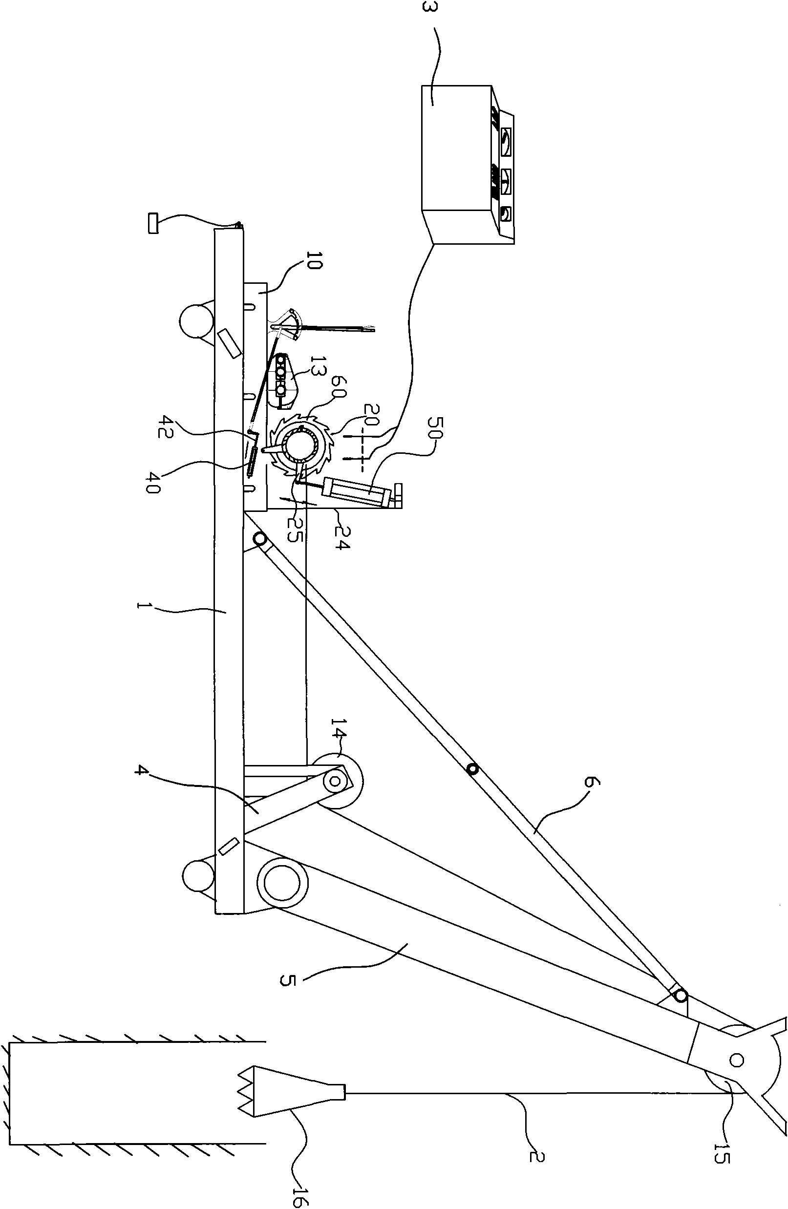
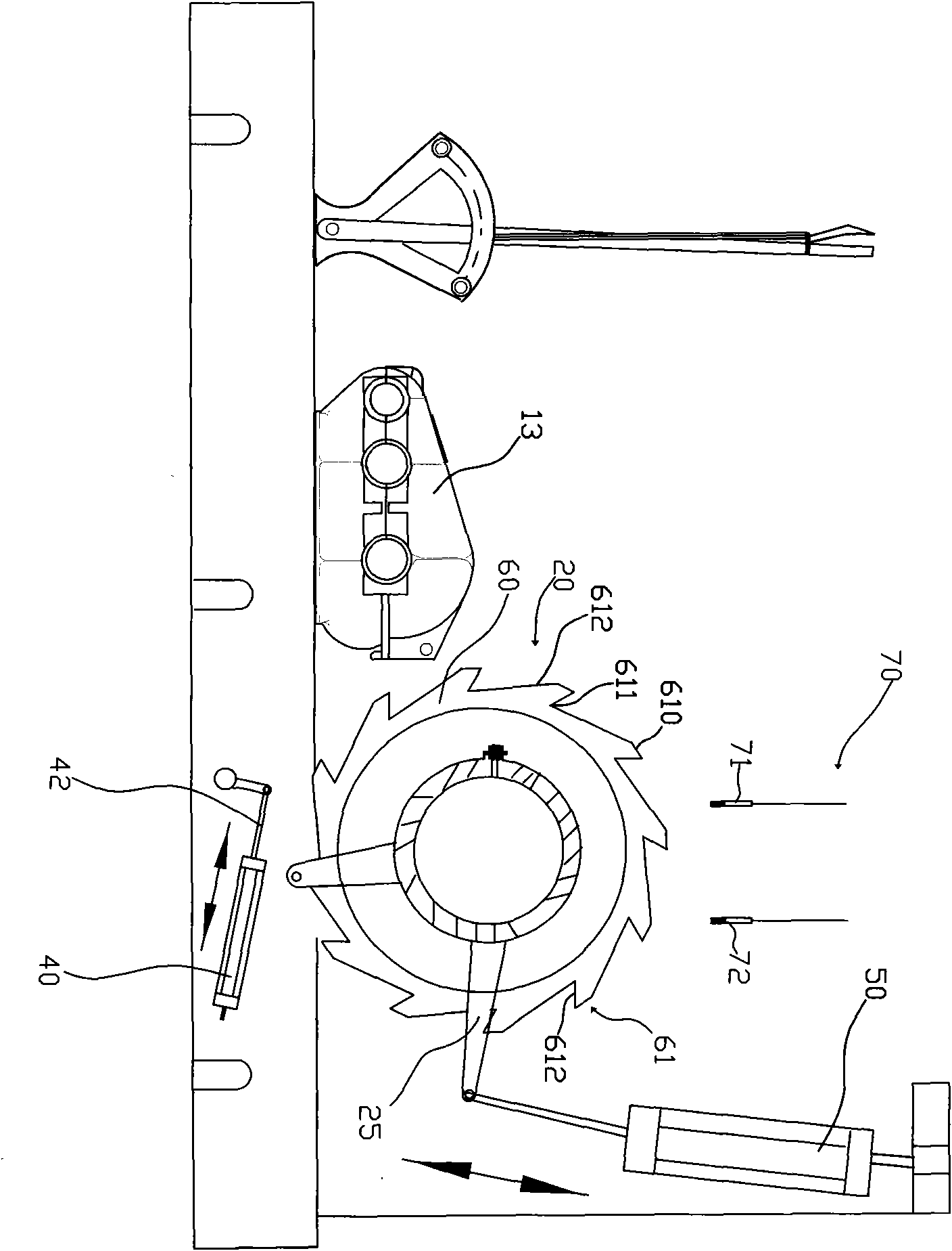
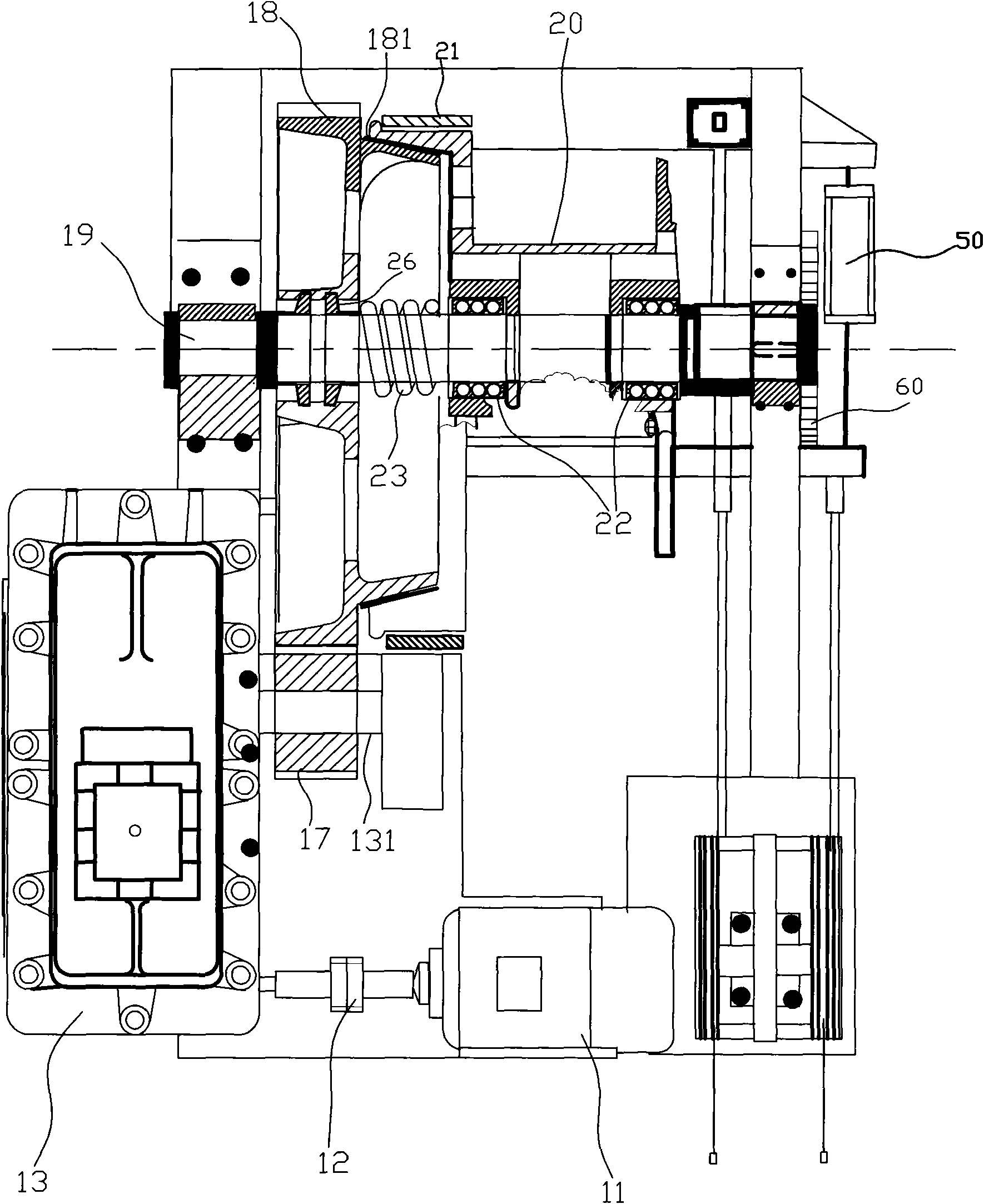
[0032] Such as Figure 1 to Figure 6 Shown, the present invention comprises the support 10 that is installed on the frame 1 when working, motor 11, reduction box 13, fixed shaft 19, reel 20, the first fixed pulley 14, the second fixed pulley 15, a wire rope 2 and weight 16, of which:

[0033] The frame 1 is also provided with a first support 4, a second support 5 and a pull rod 6. The height of the first support 4 is equivalent to or slightly higher than the height of the reel 20 and is mounted on the frame. 1 near the front end, the first fixed pulley 14 is installed on the first support; The inclination direction between the racks 1 is connected by a pull rod 6, and a second fixed pulley 15 is installed on the top of the second bracket 5;

[0034] Described electric motor 11 is installed on the machine base 10 and provides power for punch pile driver of ...


PUM


Abstract

The invention relates to an automatic punching pile driver comprising a frame, a base, a motor, a reduction gearbox, a reel, two fixed pulleys, a steel cable and a counter weight connected to one end of the steel cable, wherein an output shaft of the reduction gearbox is connected with a small gear, a large gear is meshed with the small gear, the large gear is sheathed on a fixed axis, and the reel and the large gear are in a separable tapered friction plate type connection. The external end of the reel is concentrically provided with a disk type gear, the outer edge of the disk type gear is distributed with a plurality of crowned teeth at intervals, and the external end of the reel is also provided with a programmable logic controller (PLC). Two sensor, which are used for sensing the rotation of the crowned teeth and are electrically connected with PLC, are arranged above the disk type gear, the PLC can calculate the moving direction and the distance of the steel cable through sensing the rotation direction of the crowned teeth and the number of the crowned teeth passing the sensors by the sensors, so the upward and downward motion of the counter weight can be controlled so as to further realize the automatic control of the punching process.

Description

technical field [0001] The invention relates to engineering pile-making equipment for water conservancy and hydropower, transportation ports, highways, railway systems, etc., and is particularly related to an automatic punching pile machine. Background technique [0002] At present, in the construction of roads and bridges, especially in the context of the country's vigorous development of transportation, in the construction process of elevated railways, elevated highways, and bridge piers, the piers need to be fixed in the underground rock layer to ensure the stability of the bridge. Therefore, in the formation of pier holes, it is necessary to ensure that the depth of the pier holes reaches the rock layer. In this way, special equipment is required to drill holes into the ground, and during the drilling process, the excess soil / slurry and gravel should be squeezed into the ground. The sides of the hole or clear out, in order to continuously continue to drill down. [0003...

Claims


Application Information

Patent Timeline
Patent Type & Authority Applications(China)
IPC IPC(8): E21B1/02
Inventor 顾鹏程
Owner 如皋市名门电气材料有限公司
Learn More