Method and device for testing heat transfer performance of fin surface of plate-fin heat exchanger

A plate-fin heat exchanger, heat transfer performance technology, applied in the field of heat transfer and heat exchangers, can solve the problems of difficult heat exchangers, complex equipment, not easy to obtain, etc., and achieve fewer measurement parameters and simple measurement devices , the effect of high measurement accuracy

Active Publication Date: 2011-07-27
ZHEJIANG YINLUN MACHINERY
View PDF5 Cites 38 Cited by
  • Summary
  • Abstract
  • Description
  • Claims
  • Application Information

AI Technical Summary

Problems solved by technology

[0007] The disadvantage of the first Wilson graphic method is that it needs to assume the fixed power exponent expression form of Reynolds number Re and Nusselt number Nu of one side of the fluid, which is often not easy to obtain; and in order to obtain a better approximation In order to meet the accuracy, many test data points must be tested during the test; and the whole experimental test equipment is relatively complicated, requiring two flowmeters, 6 temperature sensors, etc.
[0008] The second method of thermal resistance separation has the disadvantage that the surface heat transfer coefficient of the fluid on one side must be known before the thermal resistance separation method can be performed.
This requires that the fluid channel on one side must be designed and processed into a standard channel or a smooth channel, which is often difficult in the design process of the heat exchanger

Method used


Image

  • Method and device for testing heat transfer performance of fin surface of plate-fin heat exchanger
  • Method and device for testing heat transfer performance of fin surface of plate-fin heat exchanger
  • Method and device for testing heat transfer performance of fin surface of plate-fin heat exchanger

Examples


Embodiment Construction

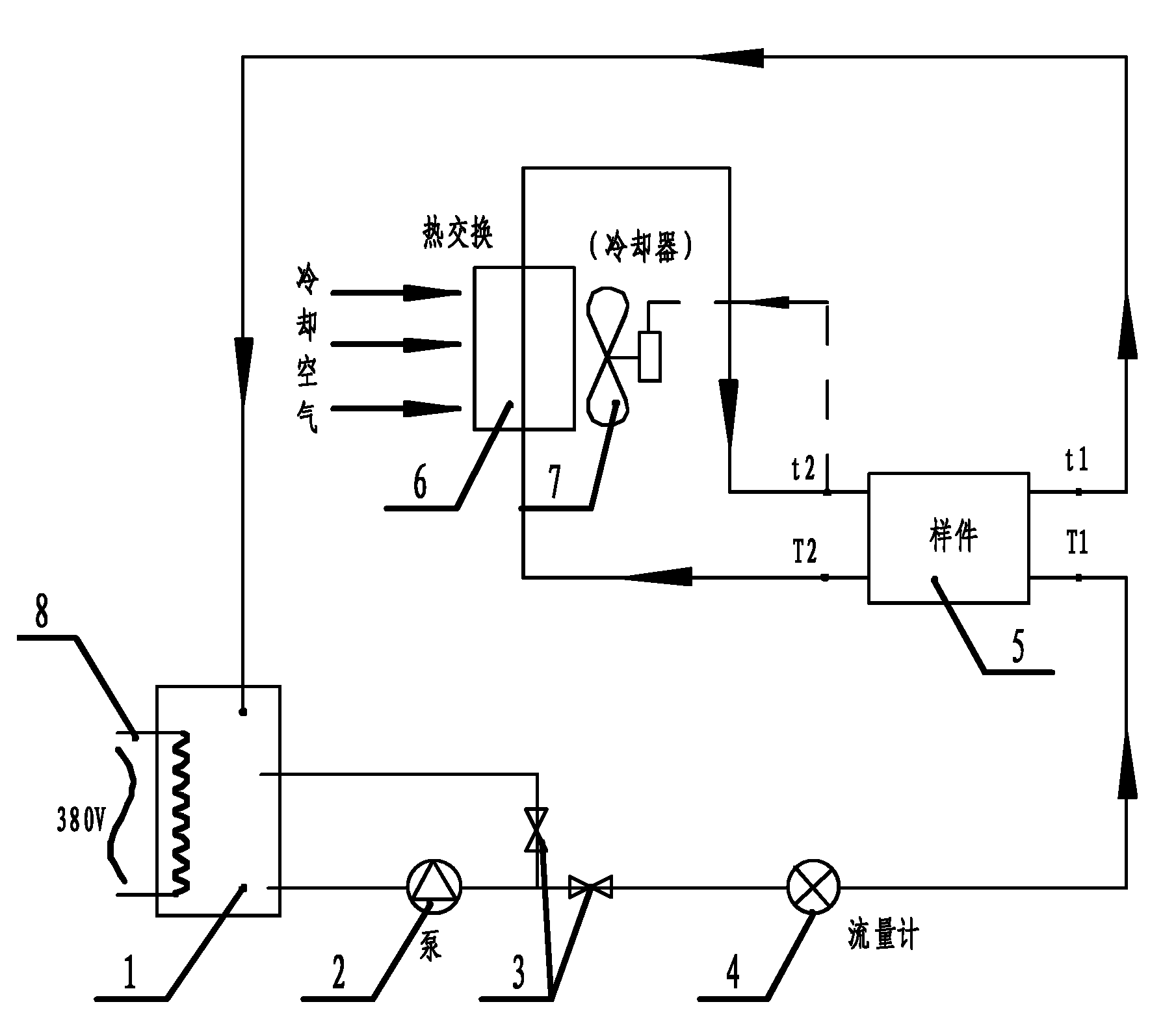
[0047] refer to figure 1 , the plate-fin heat exchanger fin heat transfer characteristic test device of the present invention is composed of a liquid heating container 1, an electric heater and its corresponding heating power adjustment device 8 controlled by a thyristor, a liquid pump 2, an adjustment Valve 3, mass flow meter 4, plate-fin heat exchanger fin test sample 5, air cooler 6, electronic fan 7 and corresponding various pipelines, 4 temperature sensors, high-precision data acquisition instrument and computer measurement and control software composition. The structure of the high temperature side and the low temperature side of the experimental sample 5 is the same, and four temperature sensors are respectively arranged at the inlet and outlet of the high temperature side and the low temperature side. Its working liquid medium adopts water.

[0048]The working cycle flow of the working medium (water) is: first, the water is heated to the set temperature by the heater...


PUM


Abstract

The invention discloses a method and a device for testing heat transfer performance of a fin surface of a plate-fin heat exchanger. The device comprises a heating container, a pump, a valve, a flow meter, an experiment sample, a cooler used for cooling liquid, a connecting pipeline, a liquid medium, a data acquisition instrument and a computer by which a circulation loop is formed. Heat transfer thermal resistance of one side is separated by testing the flow of the liquid medium passing through the heat exchanger and the temperature of four inlets / outlets in real time and utilizing the principle of equal surface thermal resistance of a high-temperature side and a low-temperature side and thermal resistance separation, and a functional relation between the high-temperature side and the low-temperature side is further obtained by calculating heat transfer coefficient h of the fin surface and flow Reynolds number Re according to structural parameters and serves as basic data for design and calculation of the heat exchanger; moreover, a functional relation obtained from new fins serves as a reference and a basis for comparing and judging mould abrasion, service life and mould repair and is simultaneously used for comparing performance difference among the fins with different structural parameters. The method has the advantages of few measurement parameters, simple measurement device and high measurement accuracy.

Description

technical field [0001] The invention relates to the technical field of heat transfer and heat exchangers, in particular to a test method and a test device for the heat transfer characteristics of the fins of a plate-fin heat exchanger. Background technique [0002] Due to its compact structure and high heat transfer efficiency, plate-fin heat exchangers are widely used in automotive, chemical, aerospace and other fields. The plate-fin heat exchanger uses two working fluids with different inlet temperatures to flow inside the heat exchanger to transfer heat. Among them, the most critical parameter affecting the heat transfer performance of the plate-fin heat exchanger is the structure of various fins inside the plate-fin heat exchanger. The form and structural parameters of different structures have very large differences in heat transfer characteristics at different fluid flow rates. How to obtain more efficient and compact plate-fin heat exchanger fins and how to quantita...

Claims


Application Information

Patent Timeline
Patent Type & Authority Applications(China)
IPC IPC(8): G01N25/20
Inventor 董军启陈一中刘浩陈启安
Owner ZHEJIANG YINLUN MACHINERY
Why Eureka
Try Eureka