
Photovoltaic cell array with mechanical uncoupling of the cells from the carrier thereof

A technology of photovoltaic cells and arrays, applied in the direction of photovoltaic power generation, photovoltaic modules, support structures of photovoltaic modules, etc., which can solve problems such as impact, loss of effectiveness, and consumption

Inactive Publication Date: 2011-07-27
THALES TOUR CARPE DIEM PLACE DES COROLLES ESPLANADE NORD COURBEVOIE
View PDF3 Cites 2 Cited by
  • Summary
  • Abstract
  • Description
  • Claims
  • Application Information

AI Technical Summary

Problems solved by technology

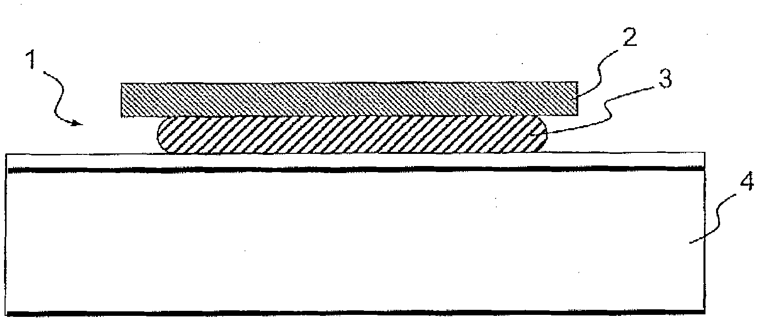
[0004] Furthermore, fixing by gluing causes the problem that the cell may have to be repaired, which is laborious since the insulating material applied to the substrate must be scraped off very finely, such as Kapton TM
According to estimates, the operation to remove the battery from its substrate can take about a day's work
[0005] Bonding the battery to the substrate tends to deform the battery
One way of mechanically decoupling the battery from the substrate involves thickening the adhesive layer, but this significantly increases the overall mass and introduces the risk of uncontrolled anarchic degassing of the adhesive, which may even cause the battery to explode (known as the "pop-off" phenomenon)
[0006] The problem with flexible battery fixation systems (such as "filaments", "membranes", etc.) is the severe technical breakage of the solar generator structure, and when the fixation of the batteries is performed on the flexible wings, it introduces a AOCS ("Attitude Over Orbital Control System") Problems
[0007] The idea of ​​mechanically decoupling a cell to its supporting substrate without considering thermal aspects is inappropriate because mechanical decoupling results in a loss of conductive coupling and must be replaced by radiative coupling
With loss of cell-substrate thermal coupling, the cell will heat up and lose most of its effectiveness

Method used


Image

  • Photovoltaic cell array with mechanical uncoupling of the cells from the carrier thereof
  • Photovoltaic cell array with mechanical uncoupling of the cells from the carrier thereof
  • Photovoltaic cell array with mechanical uncoupling of the cells from the carrier thereof

Examples


Embodiment Construction

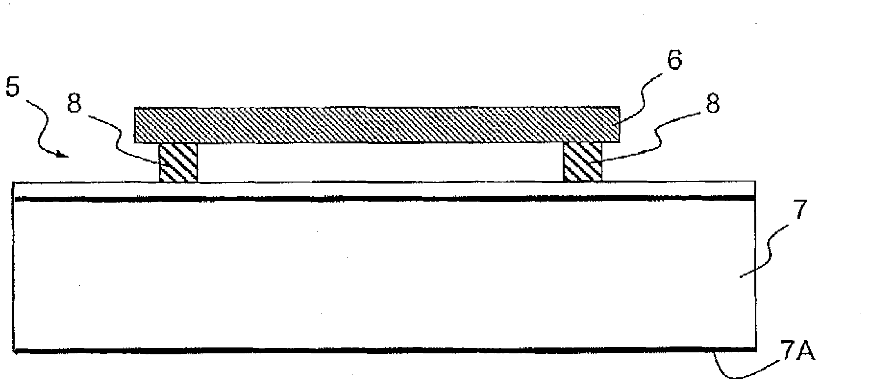
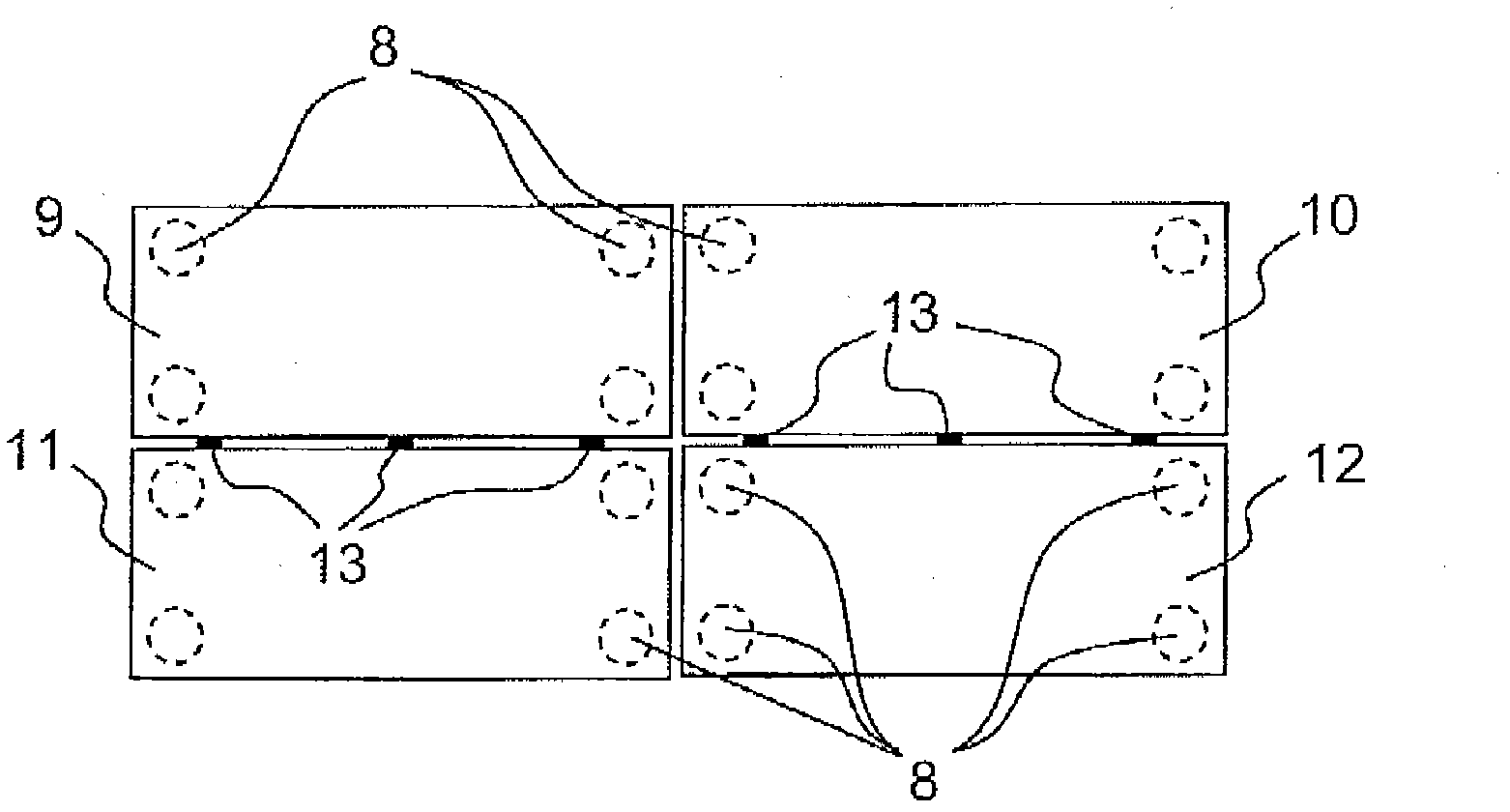
[0015] The present invention proposes a solution for reducing the mechanical coupling of the photovoltaic array of the solar generator relative to the supporting substrate of the photovoltaic array. In practice, photovoltaic cells are thin (tens of microns thick) and fragile. When a photovoltaic cell is bonded to a substrate, it undergoes geometric deformation due to vibrations, especially thermoelastic effects, which can lead to cell rupture. The invention consists of securing the battery by means of a flexible system, enabling the decoupling of the battery from the deformable part of the substrate, while ensuring sufficient radiative coupling of the battery towards the substrate, so as to avoid heating of the substrate in flight and loss of its effectiveness. This solution consists in the use of photovoltaic cells with high emissivity backsides (grid or Kaptoning backsides of Ge or Ag substrates are used) fixed on the substrate by means of Velcro.

[0016] figure 2 The ph...


PUM


Abstract

The present invention proposes a solution for reducing the mechanical coupling of the photovoltaic array of a solar generator relative to the bearing substrate thereof. A photovoltaic cell is very thin (some tens of microns) and very fragile. When the photovoltaic cell is bonded to a substrate, the cell is subjected to all the geometrical deformations caused by vibrations, and in particular to thermo-elastic effects that can lead to the breakage of the cell. The invention comprises securing the cell via a flexible system (8) that enables the uncoupling of the cell (6) from the substrate (7) deformations while maintaining a sufficient radiating coupling of the cell to the substrate in order to avoid the heating thereof in an aerial condition and any loss of efficiency. The solution comprises using photovoltaic cells with a back surface having a high emissivity (using, at the rear, a metallisation or kapton application on the Ge or Ag substrate) that is placed on the substrate using Velcro.

Description

technical field [0001] The present invention relates to an array of photovoltaic cells with a support substrate in which the cells of the array are mechanically decoupled with respect to their rigid support substrate, the array is commonly used in the manufacture of solar generator panels to ensure the power supply of spacecraft, in particular It's powered by satellites. Background technique [0002] figure 1 An exemplary embodiment of a prior art photovoltaic element 1 (also referred to as a "covered interconnected cell" or "solar module"), which forms part of an array, is shown schematically in , the array includes hundreds to tens of thousands of such elements. Element 1 comprises photovoltaic cells 2 secured by a layer of adhesive 3 to a common rigid substrate 4 of a plurality of cells. [0003] In such arrays, the photovoltaic cells are fragile because of their small thickness and are very sensitive to the deformations usually applied to them due to their adhesion to...

Claims


Application Information

Patent Timeline
IPC IPC(8): H01L31/052H01L31/042
CPCF24J2/5245H01L31/052H01L31/0422F24J2002/4659Y02E10/50Y02E10/47H02S20/00F24S25/61F24S2025/016F24S2025/6001
Inventor L 达布里容
Owner THALES TOUR CARPE DIEM PLACE DES COROLLES ESPLANADE NORD COURBEVOIE
Learn More