Eureka AIR delivers breakthrough ideas for toughest innovation challenges, trusted by R&D personnel around the world.

Excavating drilling machine

A technology for excavating drilling rigs and drill bits, which is applied in the direction of drill bits, earthwork drilling, drilling equipment, etc. It can solve the problems of large rotary drilling rigs, low hole forming efficiency, landslides, etc., and achieves high site adaptability, improved stability, The effect of reducing flatness requirements

Active Publication Date: 2011-08-03
STATE GRID CORP OF CHINA +2
View PDF10 Cites 2 Cited by
  • Summary
  • Abstract
  • Description
  • Claims
  • Application Information

AI Technical Summary

Problems solved by technology

[0002] At present, the excavation of the foundation of domestic transmission lines is excavated manually with small tools (shovels, simple cranes), the efficiency of hole formation is low, collapse may occur during the construction process, and the safety risk is high
Xiangjiaba-Shanghai, Jinping-Sunan ±800kV UHV DC transmission project adopts large section 6×720mm 2 and 6×900mm 2 Conductors, compared with ultra-high voltage transmission lines, have a larger excavation foundation design size, if the manual excavation process is still used, the construction difficulty and safety risks will further increase
[0003] Since the basic structure of transmission line excavation is the upper straight hole and the bottom enlarged hole, if the rotary drilling rig widely used in the construction industry is used for mechanized excavation, only the straight hole can be drilled, and the bottom enlarged hole is still Manual excavation is required, and the safety risks caused by manual excavation cannot be fundamentally changed
[0004] In addition, since the construction sites of transmission lines are mostly complex terrain conditions such as mountainous gullies, the trafficability of vehicles is poor, and the existing rotary drilling rigs are too large to be suitable for foundation excavation operations of transmission lines

Method used


Image

  • Excavating drilling machine
  • Excavating drilling machine
  • Excavating drilling machine

Examples


Embodiment Construction

[0020] In order to further explain the technical means and effects that the present invention takes to achieve the predetermined invention purpose, below in conjunction with the accompanying drawings and preferred embodiments, the specific implementation, structure, features and effects of the excavation drilling rig proposed according to the present invention are as follows: The details are as follows.

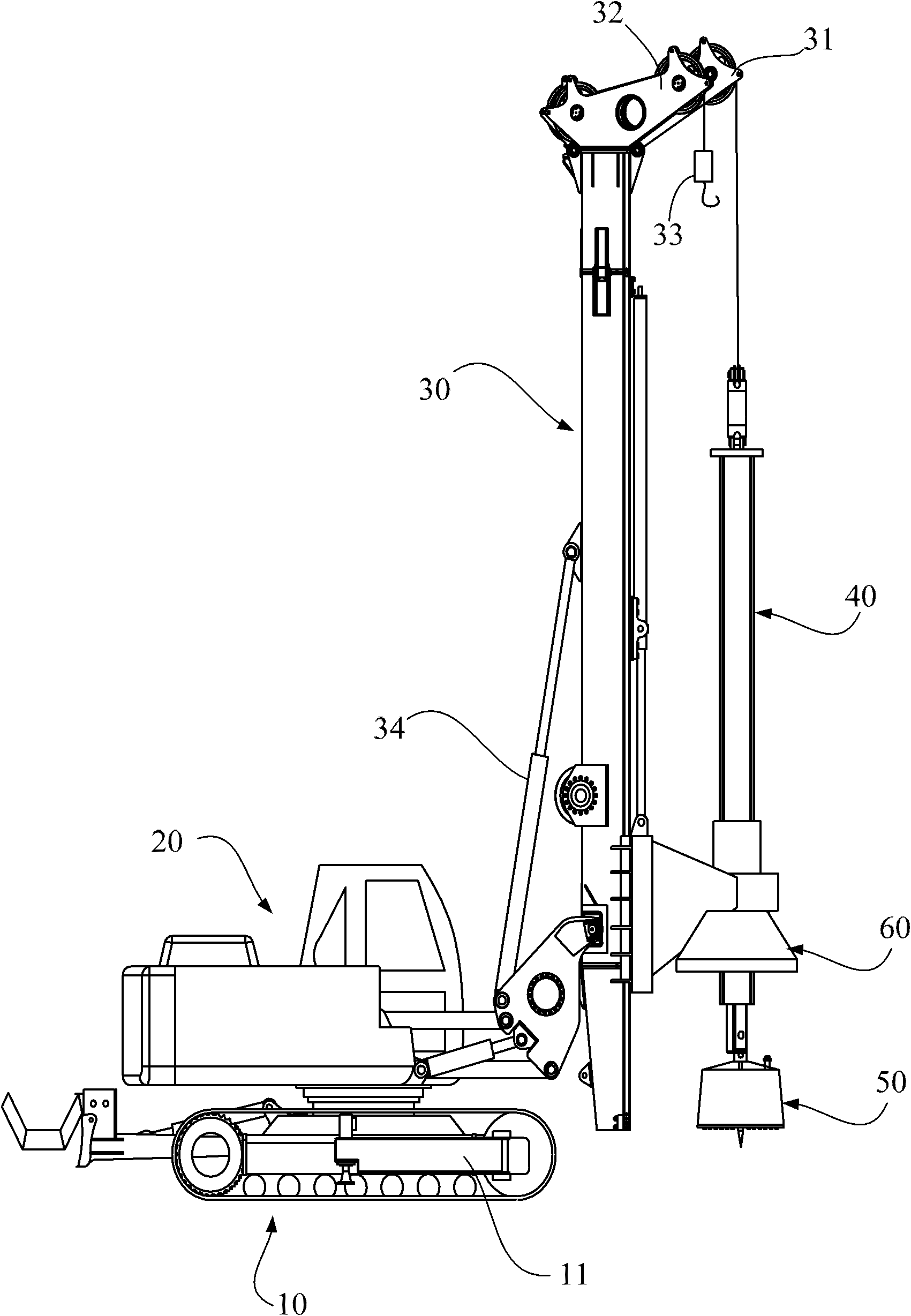
[0021] see figure 1 As shown, the excavation drilling rig of the preferred embodiment of the present invention mainly includes: chassis 10, upper car 20, mast 30, drill rod 40 and drill bit, upper car 20 is provided with hydraulic system and electric control system. The chassis 10 of the digging rig of the present invention adopts the chassis of a small excavator, preferably adopts the chassis of a Yuchai YC135 type excavator. The technical parameters of the chassis are shown in Table 1.

[0022] Table 1 Main technical parameters of Yuchai YC135 excavator chassis

[0023] ...


PUM


Abstract

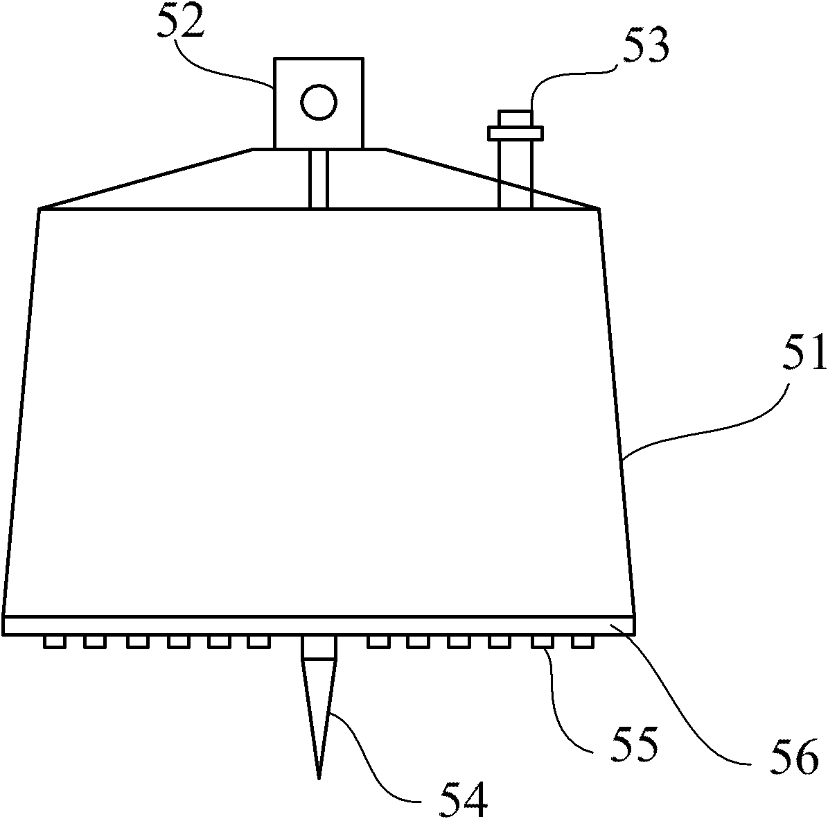
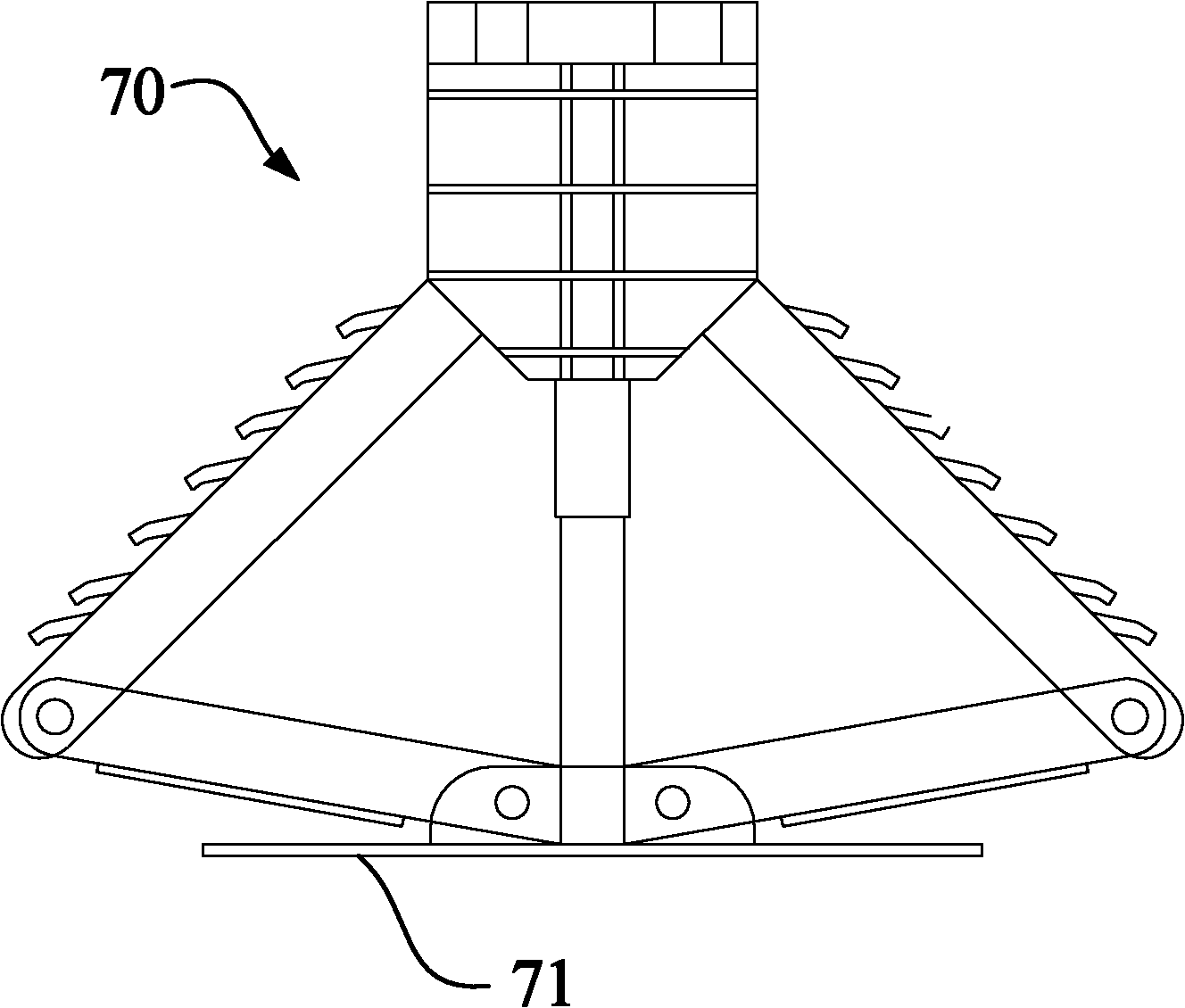
The invention relates to an excavating drilling machine comprising a base, an upper lathe, a mast, a drill rod and a drill head, wherein the upper lathe is provided with a hydraulic system and an electronic control system; and the drill head comprises a straight hole drill head and a bottom-expanding drill head, wherein the straight hole drill head and the bottom-expanding drill head are respectively arranged on the drill rod in an alternating way. The excavating drilling machine can simultaneously realize the straight hole drilling operation and the bottom-expanding bottom-expanded operation, that is to say, can implement the diameter-expanding excavation on the lower part of a foundation after a straight hole is drilled to a certain depth and automatically fetch the soil; and in addition, the invention can sufficiently meet the requirements for mechanized construction of the excavating foundation of an electric transmission line.

Description

technical field [0001] The invention relates to an excavation drilling rig in a field, in particular to an excavation drilling rig. Background technique [0002] At present, the excavation of domestic transmission line excavation is carried out manually with small tools (shovels, simple cranes). The efficiency of hole formation is low, and landslides may occur during the construction process, resulting in high safety risks. Xiangjiaba-Shanghai, Jinping-Sunan ±800kV UHV DC transmission project adopts large section 6×720mm 2 and 6×900mm 2 Compared with ultra-high voltage transmission lines, conductors have a larger digging foundation design. If manual digging is still used, the construction difficulty and safety risks will further increase. [0003] Since the basic structure of transmission line excavation is the upper straight hole and the bottom enlarged hole, if the rotary drilling rig widely used in the construction industry is used for mechanized excavation, only the st...

Claims


Application Information

Patent Timeline
Patent Type & Authority Applications(China)
IPC IPC(8): E21B7/02E21B10/26
Inventor 朱艳君高学彬余乐肖安全郎福堂梅丰侯先智王志勇王玮
Owner STATE GRID CORP OF CHINA
Why Eureka
Eureka Blog
Learn More