

Rotational speed image measurement technology of landing gear drop test aircraft wheel
A technology of image measurement and landing gear, which is applied in the direction of measuring device, impact test, machine/structural component test, etc., can solve the problems of difficult design and installation, heavy weight, etc., and achieve increased equipment cost, simple and good rotational speed measurement structure The effect of dynamic response performance
- Summary
- Abstract
- Description
- Claims
- Application Information
AI Technical Summary
Problems solved by technology
Method used
Image

Examples
Embodiment 1
[0031] Embodiment 1: the steps of the image measurement technique of the wheel speed are:
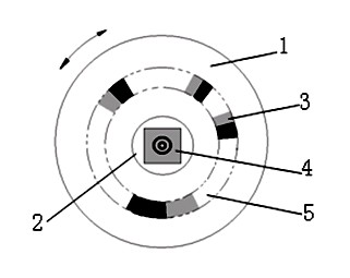
[0032] 1) Set the axle mark 4 at the center of the wheel axle 2, and at the same time select a virtual ring area 5 at an appropriate position on one side of the wheel hub 1, and set several wheel marks 3 at unequal intervals;
[0033] The color of the mark should be conducive to forming a high-contrast image, such as black and white; the shape of the axle mark should be conducive to determining the position of the point through the image, such as circle, ring, multi-ring, diagonal, cross, etc., by calculating the square or extracting corner points to obtain the coordinates of its feature points; the two color blocks of the wheel mark 3 should have sufficient length along the circumference to reduce the adverse effects caused by motion blur, and the boundary line of the two colors should follow the direction of the wheel. Radial to facilitate the matching and positioning of the image alo...
Embodiment 2
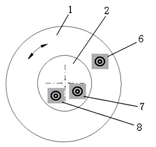
[0040] Example 2: see image 3 , the steps of image measurement technology of wheel speed are:
[0041] When the axle 2 is a brake disc, if the axle mark 4 cannot be set in its center, the center coordinates of the axle 2 can be obtained by the following method:
[0042] 1) Paste B mark 7 and C mark 8 on the brake disc at a position separated by a large distance, and then paste A mark 6 on the flat side of the wheel hub or tire;
[0043] 2) if Figure 4 , install the camera, and the installation requirements are basically the same as step 2 in embodiment 1);
[0044] 3) Keep the center of the wheel axle 2 stationary, and the brake disc is also stationary, and at the same time turn the wheel to different angles and capture corresponding images;
[0045] 4) Locate the mark in the acquired image, and obtain the center coordinate value of the corresponding mark. Make a circle fit to the position of the center of A mark 6 under each rotation angle of the wheel to obtain the coor...
Embodiment 3
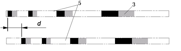
[0049] In the case that there is a wheel fork on the imaging surface of the wheel 1, with the rotation of the wheel 1, a part of the ring mark area 5 where the wheel mark 3 is located is always partially covered, and at this time only the rotational speed in Example 1 needs to be calculated. in the process of figure 2 Make a small improvement in the registration process of the two frames of images in the following method:
[0050] 1) Generally, the rotation range of the wheel fork relative to the wheel shaft 2 is limited. Even if it is a rocker landing gear, the rotation range of the wheel fork cannot reach 180 degrees. Therefore, the ring mark area 5 where the wheel mark 3 is located always has most Unoccluded by the wheel fork, and its orientation on the image is fixed. First specify this unoccluded area in some simple form according to the actual situation;
[0051] 2) The unoccluded area also has a corresponding range in the flat map after the polar coordinate transform...
PUM
 Abstract
Description
Claims
Application Information