
Optical device and fabrication method thereof

A technology for optical devices and optical couplers, applied in the field of optical devices, which can solve the problems of high related cost, large size, and complexity

Active Publication Date: 2011-08-03
SAMSUNG ELECTRONICS CO LTD
View PDF6 Cites 24 Cited by
  • Summary
  • Abstract
  • Description
  • Claims
  • Application Information

AI Technical Summary

Problems solved by technology

This results in large and complex devices, modules and systems and also in higher associated costs

Method used


Image

  • Optical device and fabrication method thereof
  • Optical device and fabrication method thereof
  • Optical device and fabrication method thereof

Examples


Embodiment Construction

[0131] Various exemplary embodiments will be described more fully hereinafter with reference to the accompanying drawings, in which some exemplary embodiments are shown. However, inventive concepts may be embodied in many different forms and should not be construed as limited to the exemplary embodiments set forth herein.

[0132] It will be understood that when an element or layer is referred to as being "on," "connected to" and / or "coupled to" another element or layer, it can be directly on or directly connected to the other element or layer. to, coupled to, another element or layer, or intervening elements or layers may be present. In contrast, when an element is referred to as being "directly on," "directly connected to" and / or "directly coupled to" another element or layer, there are no intervening elements or layers present. Like reference numerals designate like elements throughout. As used herein, the term "and / or" includes any and all combinations of one or more of ...


PUM


Abstract

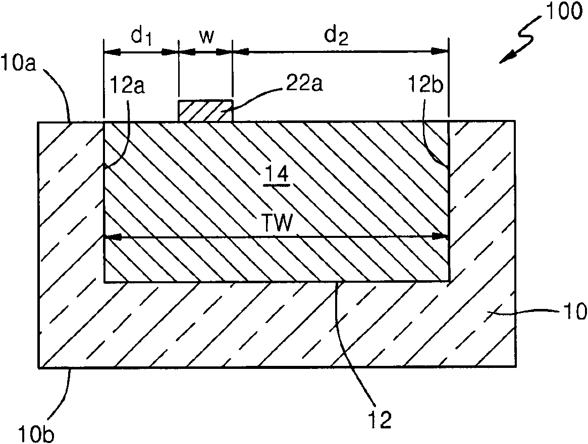
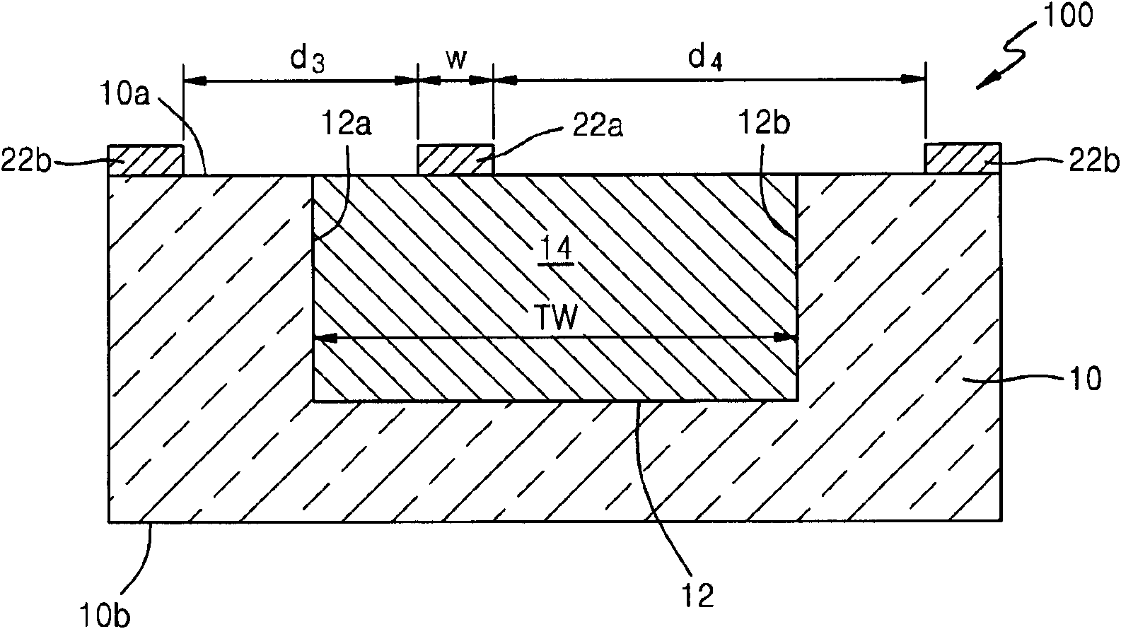
The present invention relates to an optical device and a fabrication method thereof. Optical waveguide and coupler devices include a trench formed in a bulk semiconductor substrate, for example, a bulk silicon substrate. A bottom cladding layer is formed in the trench, and a core region is formed on the bottom cladding layer. A reflective element, such as a distributed Bragg reflector can be formed under the coupler device and / or the waveguide device. Because the optical devices are integrated in a bulk substrate, they can be readily integrated with other devices on a chip or die in accordance with silicon photonics technology. Specifically, for example, the optical devices can be integrated in a DRAM memory circuit chip die.

Description

technical field [0001] The inventive concepts relate to optical devices and methods, and more particularly, to optical waveguides and optical couplers for implementing optical communications, and methods of manufacturing optical waveguides and optical couplers. Background technique [0002] Optical devices such as optical fibers, optical waveguides, and optical couplers are used for high-speed, low-power communications in a variety of devices and systems. Optical interconnects have been used in semiconductor memory devices, modules, and systems to enable high-capacity, high-speed, and low-power communications. In these systems, optical fibers can be used for communication between modules. The optical fiber can be coupled to the memory module and the memory device through the optical coupler, and the optical signal can be transmitted within the module and the memory device through the optical waveguide. [0003] Optical interconnects in memory modules, devices, and systems ...

Claims


Application Information

Patent Timeline
Patent Type & Authority Applications(China)
IPC IPC(8): G02B6/122G02B6/13G02B6/42
CPCG02B6/122G02B6/4214G02B6/30G02B2006/12104G02B6/124G02B6/34
Inventor 池晧哲金奇南邢庸宇罗敬远河镜虎朴允童裵大录卜镇权姜泌圭
Owner SAMSUNG ELECTRONICS CO LTD
Learn More