
Integrated production of self injection locked self phase loop locked optoelectronic oscillator

a technology of optoelectronic oscillators and self-injection, which is applied in the direction of oscillator generators, instruments, electrical equipment, etc., can solve the problems of high power consumption, large volume, and large amount of real estate and cost, and achieve the effect of reducing power consumption

Active Publication Date: 2014-09-18
SYNERGY MICROWAVE CORP
View PDF20 Cites 18 Cited by
  • Summary
  • Abstract
  • Description
  • Claims
  • Application Information

AI Technical Summary

Benefits of technology

The patent describes a way to create components using technology commonly found in silicon and biCMOS that can be integrated into photonic circuits. This helps reduce the need for separate microwave components. The patent also describes how to create an optoelectronic oscillation circuit that can generate a stable signal using a single voltage controlled oscillator. This circuit has significantly less power consumption and can operate at lower voltages compared to discrete components. Overall, the innovation presented in this patent helps to create more efficient and compact photonic circuits.

Problems solved by technology

Such OEOs are conventionally assembled from discrete devices, require a large volume, have high power consumption, and require a great deal of real estate and cost.
Additionally, due to the assembly of a large number of discrete parts, such OEOs are generally subject to vibration and G-sensitivity problems.
These problems limit the utility of and possible applications for OEOs in several environments, such as both commercial and military environments.
Moreover, phase noise reduction using self-ILPLL does not achieve a sufficiently commercially viable product unless major low noise and efficient design innovations are considered to accommodate a low cost manufacturing process to meet the continuously increasing demand for quality services at a lower cost.

Method used


Image

  • Integrated production of self injection locked self phase loop locked optoelectronic oscillator
  • Integrated production of self injection locked self phase loop locked optoelectronic oscillator
  • Integrated production of self injection locked self phase loop locked optoelectronic oscillator

Examples


Embodiment Construction

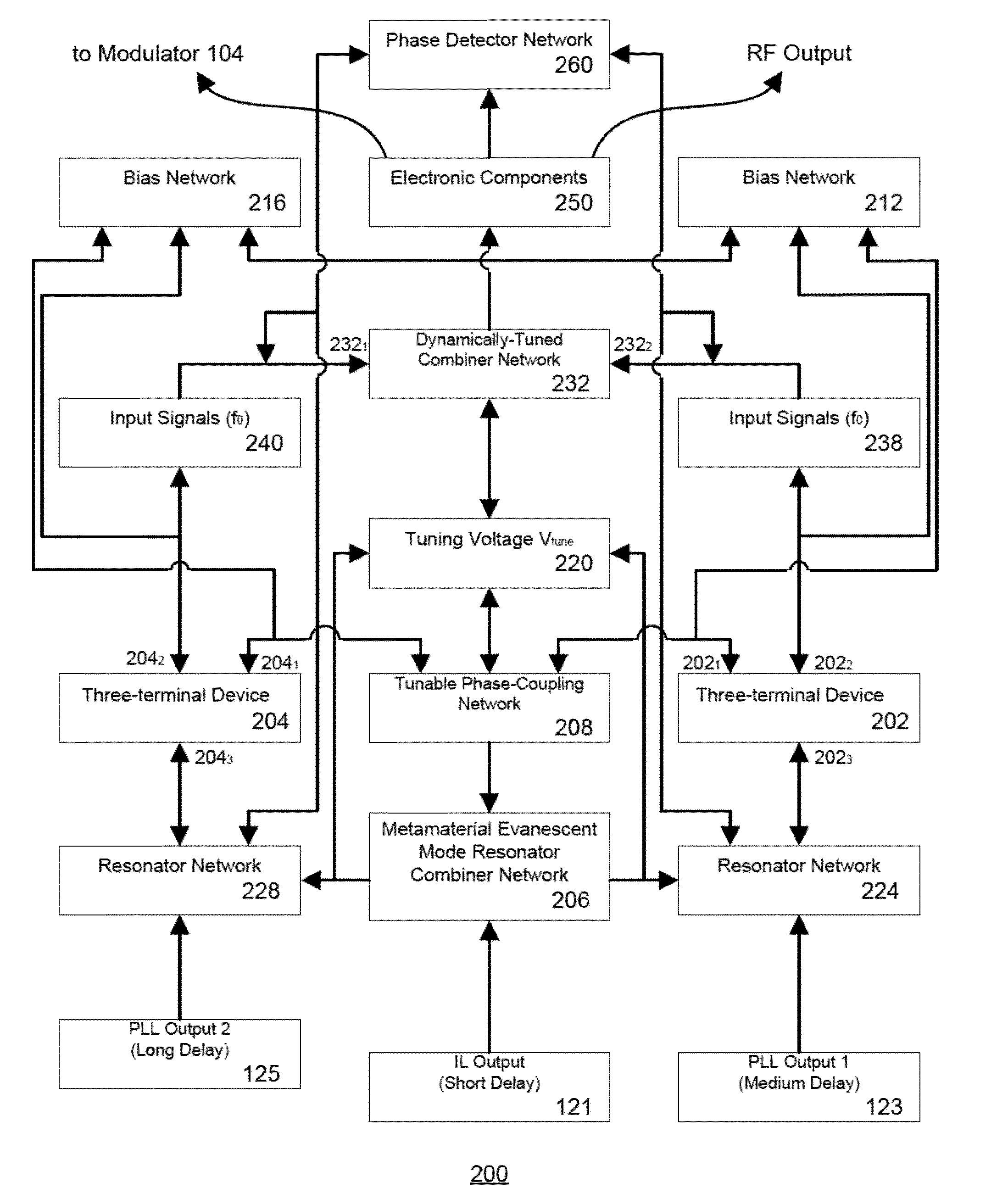
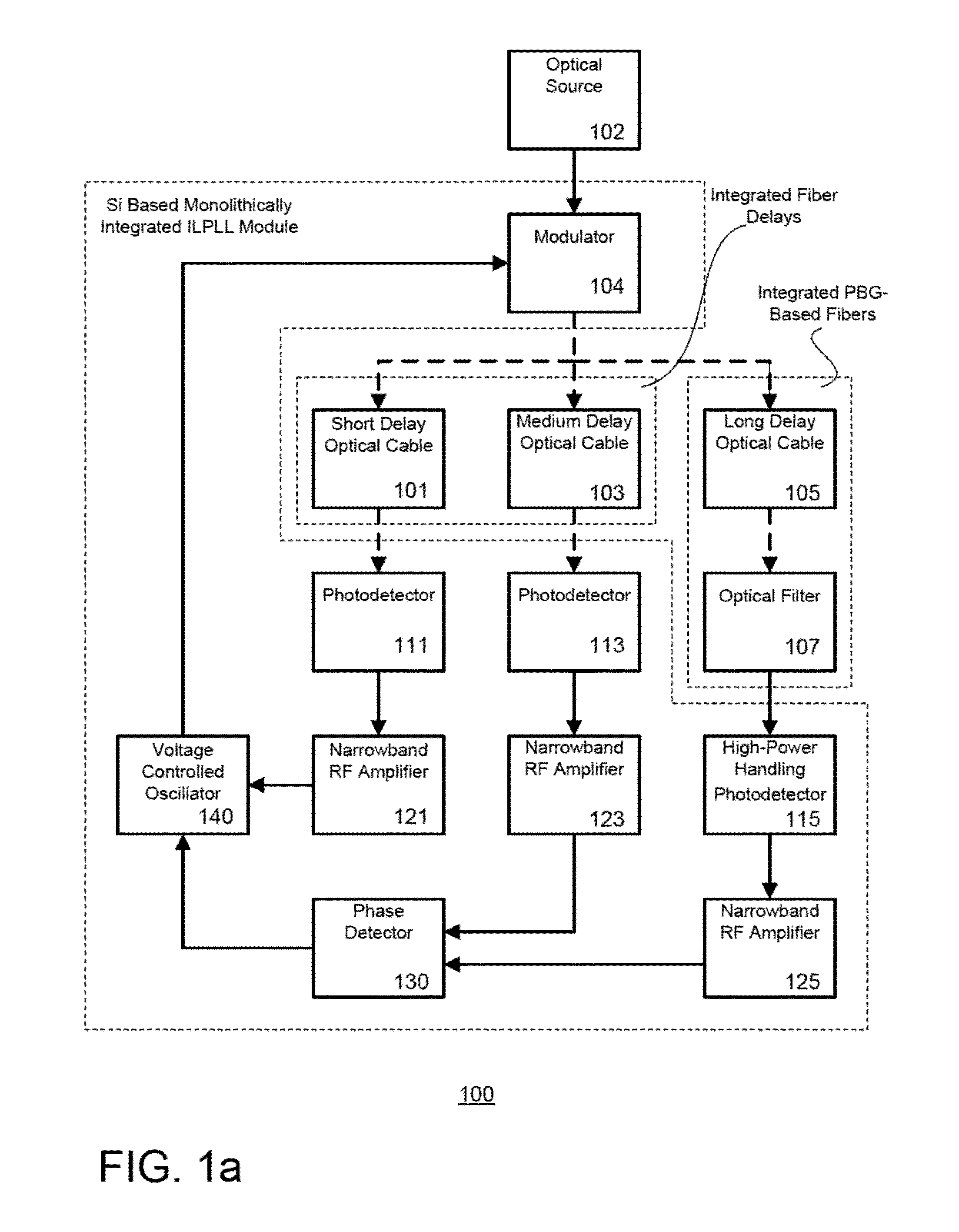
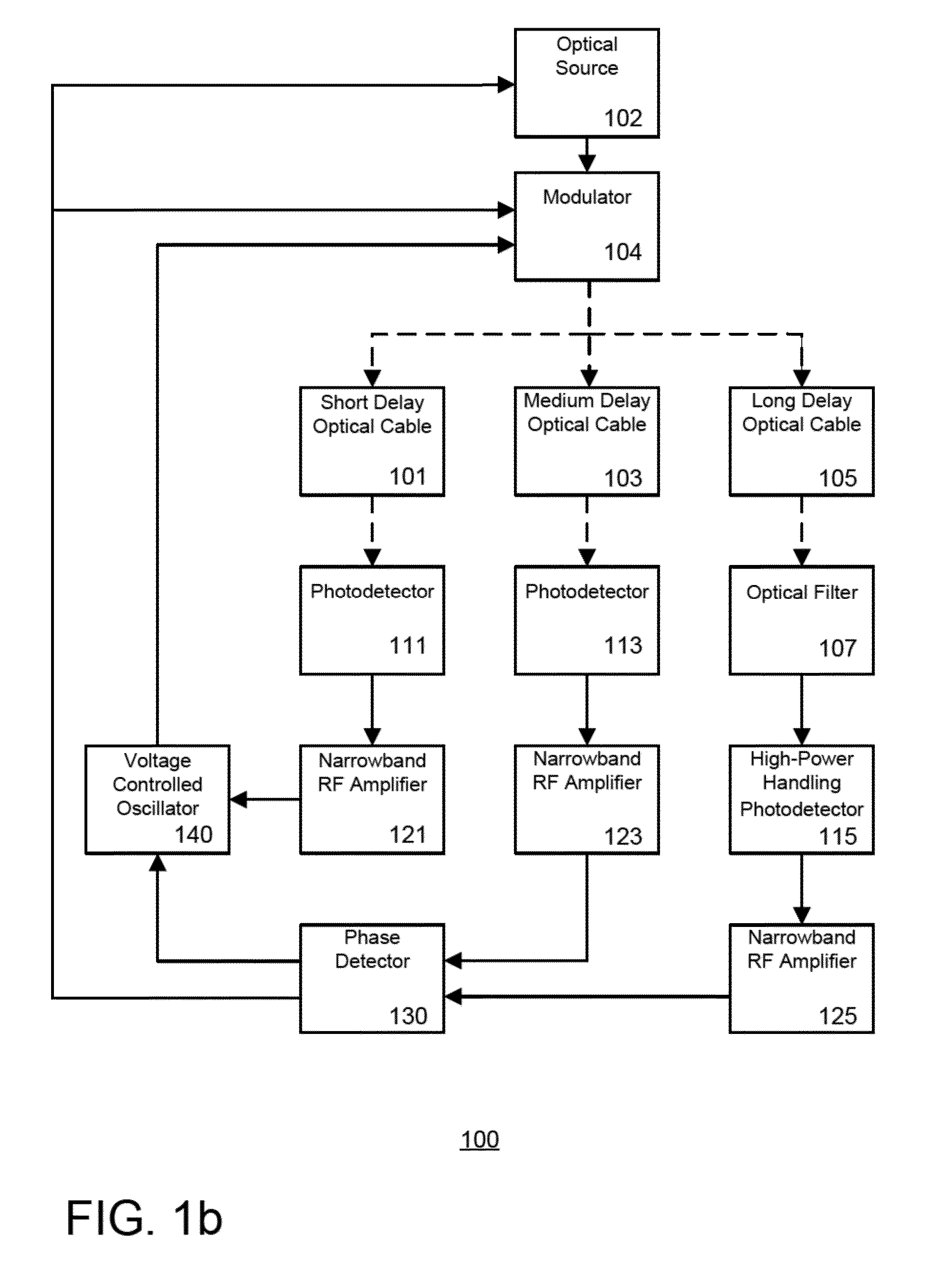
[0024]The present invention details fabrication guidelines of integrated optoelectronic oscillators with frequency and phase stability that are required for both a narrower channel resolution (due to, e.g., reduction of phase noise) as well as a more precisely locked frequency (due to, e.g., reduced temperature sensitivity) than that achieved by conventional OEO systems. As a result, data may be transmitted over a given communication bandwidth at a lower bit error rate. Moreover, the RF and optical signal, given their low phase noise characteristics, could be used as a stable clock for electrical and optical sampling of broadband information in analog to digital converters and a number of other digital processing functions.

[0025]Yet another object of the disclosure is to provide an integrated optoelectronic filtering system having higher frequency selectivity in a relatively small size (compared to the larger size of a higher order electrically realized RF filter), reduced temperatu...


PUM


Abstract

The present invention details fabrication guidelines of integrated optoelectronic oscillators with frequency and phase stability, having higher frequency selectivity in a relatively small size (compared to the larger size of a higher order electrically realized RF filter), reduced temperature sensitivity, and minimized frequency drift. The integrated photonic components and RF oscillator may use Silicon photonics and microelectronic integration using CMOS and BiCMOS technology, eliminating the need for bulky and / or discrete optical and microwave components.

Description

FIELD OF THE INVENTION[0001]This disclosure is directed to physical realization and cost efficient implementation of a system and method for controlling an optoelectronic oscillator (“OEO”). In a preferred embodiment, the OEO is capable of producing repetitive electronic sine wave and / or electrically modulated continuous wave or modulated optical signals.BACKGROUND OF THE INVENTION[0002]Generally, optoelectronic oscillators (OEO) receive pump continuous energy from an optical source, such as a laser, in addition to energy in the form of direct current (DC) power from a power supply. The energy is converted into radio frequency (RF) and microwave signals based on efficient power conversion by meeting the required gain and phase characteristics at an oscillation frequency using a narrowband filtering mechanism. The OEOs typically experience a low loss optical delay, low temperature sensitivity, and can be realized in modular structures. These benefits often lead to a high quality fact...

Claims


Application Information

Patent Timeline
Patent Type & Authority Applications(United States)
IPC IPC(8): H04B10/61
CPCH04B10/61H03B17/00H04B10/50G02F1/0121G02F1/2255G02F1/00
Inventor PODDAR, AJAY KUMARROHDE, ULRICH L.DARYOUSH, AFSHIN S.
Owner SYNERGY MICROWAVE CORP
Learn More