Grid controlled Schottky junction tunneling field effect transistor and forming method thereof

A technology of tunneling field effect and Schottky junction, which is applied in the direction of semiconductor devices, semiconductor/solid-state device manufacturing, electrical components, etc., can solve the problems of small open current, difficult gate length, and increased cost, and achieve small gate length , Excellent switching characteristics and high frequency characteristics, and the effect of increasing density

Active Publication Date: 2011-08-03
TSINGHUA UNIV
View PDF6 Cites 26 Cited by
  • Summary
  • Abstract
  • Description
  • Claims
  • Application Information

AI Technical Summary

Problems solved by technology

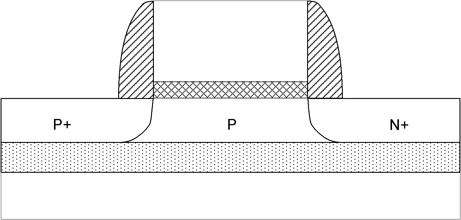
However, as TFETs continue to be scaled down, in order to obtain a larger on-state current and a smaller slope in the subthreshold region, the impurity doping concentration gradient at the P-N junction interface formed between the source region and the channel region needs to be more intense. Steep or heterojunction methods, which greatly increase the difficulty and cost of process steps
And further, the traditional gate-controlled P-I-N structure-based tunneling transistor needs to use asymmetric ion implantation in order to define the P-I-N structure, so it cannot adopt a self-aligned structure, and at the same time, due to the limitation of lithographic alignment accuracy, it is very difficult to implement. Small grid lengths are difficult
This negative effect will affect the integration of the device
In addition, fabricating such tunneling transistors will require more steps than fabricating conventional MOS transistors, thus increasing the cost of fabrication

Method used


Image

  • Grid controlled Schottky junction tunneling field effect transistor and forming method thereof
  • Grid controlled Schottky junction tunneling field effect transistor and forming method thereof
  • Grid controlled Schottky junction tunneling field effect transistor and forming method thereof

Examples


Embodiment Construction

[0034] Embodiments of the present invention are described in detail below, examples of which are shown in the drawings, wherein the same or similar reference numerals designate the same or similar elements or elements having the same or similar functions throughout. The embodiments described below by referring to the figures are exemplary only for explaining the present invention and should not be construed as limiting the present invention.

[0035] The following disclosure provides many different embodiments or examples for implementing different structures of the present invention. To simplify the disclosure of the present invention, components and arrangements of specific examples are described below. Of course, they are only examples and are not intended to limit the invention. Furthermore, the present invention may repeat reference numerals and / or letters in different instances. This repetition is for the purpose of simplicity and clarity and does not in itself indicat...


PUM


Abstract

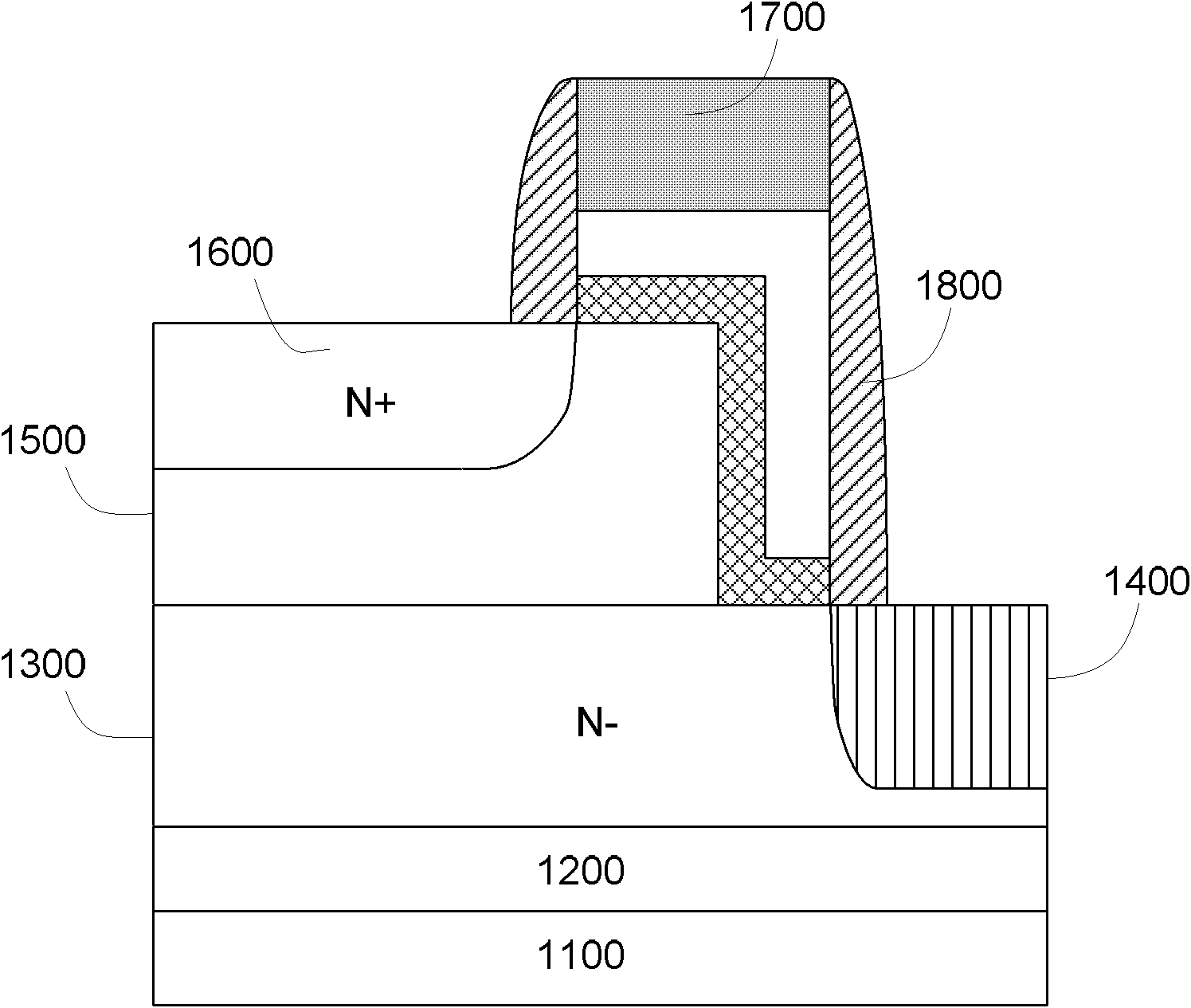
The invention provides a grid controlled Schottky junction tunneling field effect transistor, which comprises a substrate, a channel layer, a metal source region, a second semiconductor material layer, a drain region, step grid stacks and one-layer or multi-layer side walls, wherein the channel layer is formed on the substrate and made of a first semiconductor material, and the channel layer is provided with a channel region; the metal source region is formed in the channel layer and adjacent to the channel region, wherein the metal source region and the channel region form a Schottky junction; the second semiconductor material layer is formed on the first region of the channel layer; the drain region is formed in the second region of the second semiconductor material layer; the step gridstacks are formed on the third region of the channel layer and on the fourth region of the second semiconductor material layer; and the one-layer or multi-layer side walls are formed on two sides of the step grid stacks. The semiconductor structure provided by the invention has better switching property and high frequency property.

Description

technical field [0001] The invention relates to the technical field of semiconductor design and manufacture, in particular to a Gate Controlled Schottky-Barrier Tunneling Field Effect Transistor (Gate Controlled Schottky-Barrier Tunneling Field Effect Transistor) and a forming method thereof. Background technique [0002] As the feature size of the traditional MOSFET (Metal Oxide Semiconductor Field Effect Transistor, Metal-Oxide-Semiconductor Field Effect Transistor) continues to scale down, the short-channel effect of the device becomes more and more serious, and the leakage current of the device increases, making the device The ratio of the on-state current to the off-state current (that is, the switching ratio I on / I off ) keeps decreasing, which leads to the deterioration of the performance of the device. In order to save costs, these difficulties need to be overcome without resorting to new materials and process steps, so new solutions must be found. [0003] TFET ...

Claims


Application Information

Patent Timeline
Patent Type & Authority Applications(China)
IPC IPC(8): H01L29/78H01L29/423H01L29/06H01L21/336H01L21/8238H01L21/28
CPCH01L29/7391
Inventor 梁仁荣王敬许军
Owner TSINGHUA UNIV
Why Eureka
Try Eureka