Synchronous signal obtaining system and method

A technology for synchronizing signals and acquiring systems, applied in impedance networks, electrical components, multi-terminal pair networks, etc., can solve problems such as steady-state errors, difficulty in ensuring phase synchronization and accuracy, and affecting the dynamic response speed of the detection system to achieve filtering performance Good results

Inactive Publication Date: 2011-08-03
BEIJING INFORMATION SCI & TECH UNIV
View PDF0 Cites 3 Cited by
  • Summary
  • Abstract
  • Description
  • Claims
  • Application Information

AI Technical Summary

Problems solved by technology

There are three types of traditional PLL based on zero-crossing detection, stationary coordinate system and synchronous rotating coordinate system; the zero-crossing detection PLL is the simplest one, but its performance deteriorates when the frequency changes or voltage sags; the static coordinate system PLL is in the Accurate phase tracking cannot be performed under unbalanced voltage conditions; synchronous rotating coordinate system PLLs perform better under abnormal grid conditions, but performance deteriorates under unbalanced grid conditions
The phase-locked loop is generally composed of a phase detector, a loop filter and an oscillator. The filter uses a low-pass filter LPF (Low PassFilter, LPF) and a notch filter to obtain the argument information of the power grid; but the above-mentioned filter It will bring a large lag and produce a certain steady-state error; and the filter algorithm is complex, which affects the dynamic response speed of the detection system
When the grid is unbalanced or contains harmonics, and the grid frequency fluctuates around 50Hz, it is difficult for traditional PLLs to ensure phase synchronization and accuracy

Method used


Image

  • Synchronous signal obtaining system and method
  • Synchronous signal obtaining system and method
  • Synchronous signal obtaining system and method

Examples


Embodiment Construction

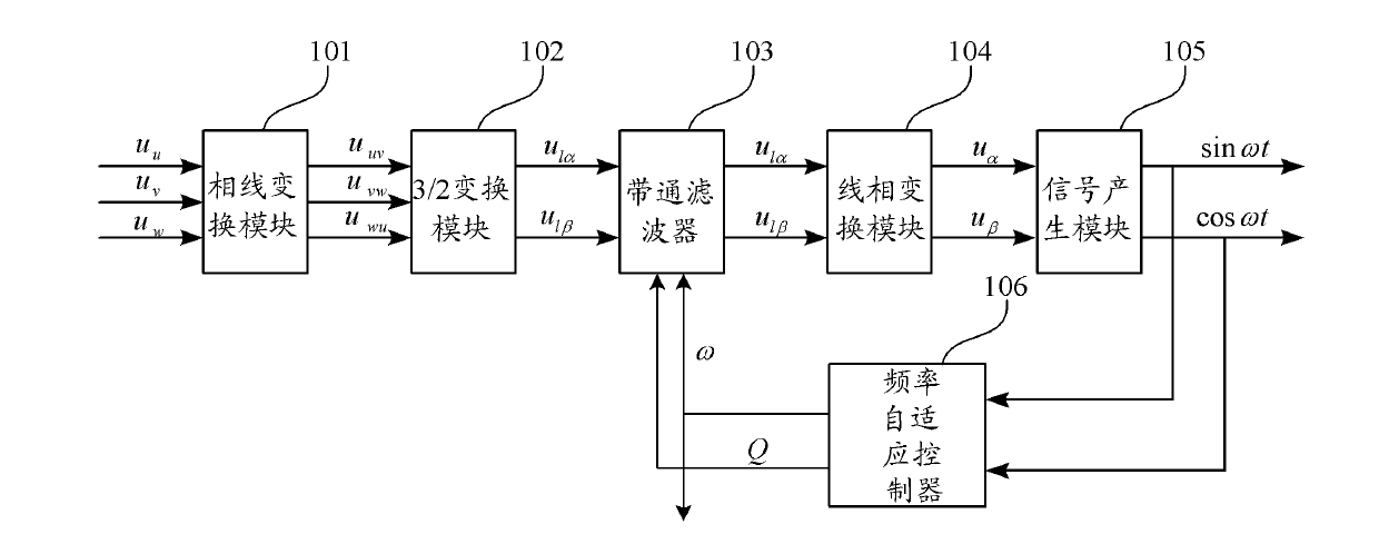
[0019] Such as figure 1 As shown, the synchronous signal acquisition system provided by the embodiment of the present invention provided by the embodiment of the present invention includes a phase-line conversion module 101, a 3 / 2 conversion module 102, a band-pass filter 103, a line-phase conversion module 104, a signal generation module 105 and Frequency adaptive controller 106 .

[0020] Among them, the phase-line conversion module 101 converts the phase voltage into the three-phase line voltage u uv , u vw , u wu , if the three-phase phase voltage can be measured, the line voltage can be calculated by the following formula

[0021] u uv u vw u wu = 1 ...


PUM


Abstract

The invention discloses a synchronous signal obtaining system and method. The system comprises a phase-line conversion module, a 3/2 conversion module, a band-pass filter, a line-phase conversion module and a signal generation module. The method comprises the following steps: converting the three-phase voltage into a three-phase line voltage; converting the three-phase line voltage into a line voltage in a two-phase static coordinate system; filtering the disturbing signals in a power grid, obtaining the sine wave with the same frequency as the power grid, and ensuring that the output signal has the same phase as the input signal; converting the line voltage in the two-phase static coordinate system into a phase voltage in the two-phase static coordinate system; and obtaining a synchronous signal based on the phase voltage in the two-phase static coordinate system. According to the synchronous signal obtaining system and method provided by the invention, due to line-phase conversion and phase-line conversion, high-performance extraction of synchronous signals can be realized in the case of unbalance or disturbance of the power grid. Moreover, as phase shift does not exist in the output and input of the band-pass filter, the filtering performance is good.

Description

technical field [0001] The invention relates to the field of power electronics and electric transmission, in particular to a synchronization signal acquisition system and method. Background technique [0002] In the design of controllers for power electronics and electric transmission devices (such as PWM rectifiers, inverters, and AC motors), in order to simplify the design and implementation of the controllers, it is usually necessary to design various controllers in the two-phase synchronously rotating dq coordinate system. The quantity in the three-phase coordinate system is transformed into the two-phase synchronously rotating dq coordinate system through the rotation transformation matrix, or the quantity in the two-phase synchronously rotating dq coordinate system is transformed into the three-phase coordinate system through the inverse rotation matrix. Synchronization signals sinωt, cosωt, and ω with the power supply are required in the rotation transformation matrix...

Claims


Application Information

Patent Timeline
Patent Type & Authority Applications(China)
IPC IPC(8): H03H7/09
Inventor 王久和
Owner BEIJING INFORMATION SCI & TECH UNIV
Why Eureka
Try Eureka