Method and device for compensating chromatic dispersion in optical communication system

An optical communication system and a dispersion compensation technology, applied in the field of optical communication, can solve the problems such as the inability to effectively compensate for the damage of the dispersion ripple signal, and achieve the effects of compensating for the dispersion ripple and compensating for the dispersion

Active Publication Date: 2011-08-03
深圳市泽信通信息工程有限公司
View PDF4 Cites 13 Cited by
  • Summary
  • Abstract
  • Description
  • Claims
  • Application Information

AI Technical Summary

Problems solved by technology

[0008] In practical application, the method of compensating the dispersion ripple in the optical communication system in the prior art has at least the following problems: the limitation of this scheme is that different frequency components of the digital signal have th

Method used


Image

  • Method and device for compensating chromatic dispersion in optical communication system
  • Method and device for compensating chromatic dispersion in optical communication system
  • Method and device for compensating chromatic dispersion in optical communication system

Examples


Embodiment 1

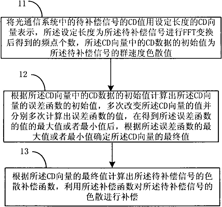
[0026] The processing flow of a method for compensating dispersion in an optical communication system provided by this embodiment is as follows figure 1 As shown, the following processing steps are included:

[0027] Step 11, express the CD value of the signal to be compensated in the optical communication system by a CD vector of a set length, the value of the set length is the number of frequency points obtained after the FFT transformation of the signal to be compensated, the The initial value of the CD data in the CD vector is the group velocity dispersion value of the signal to be compensated.

[0028] In a communication system, the same signal can be characterized by either a time-domain signal or a frequency-domain signal. Therefore, signal processing in a communication system can also be divided into time-domain processing and frequency-domain processing accordingly. domain processing. In the present invention, dispersion compensation can be performed based on signal...

Embodiment 2

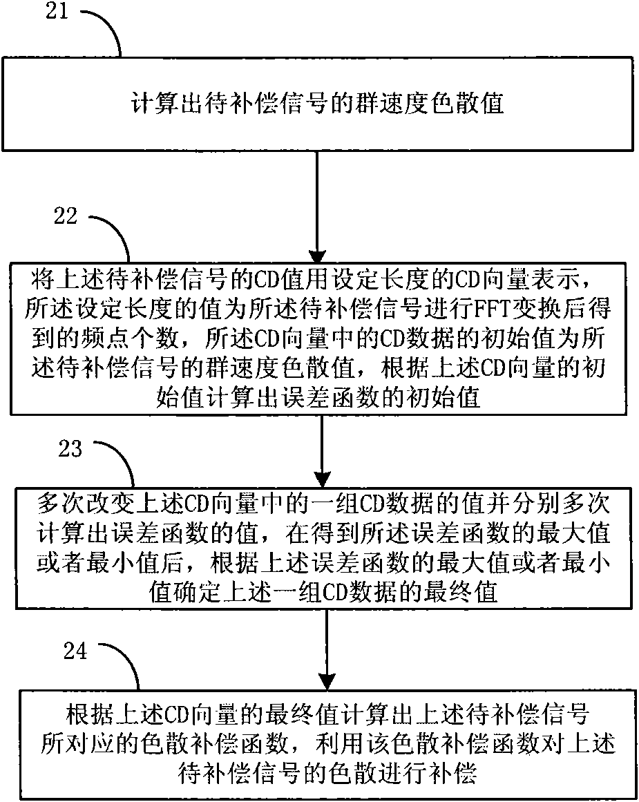
[0044] The processing flow of a method for compensating dispersion in an optical communication system provided by this embodiment is as follows figure 2 As shown, the following processing steps are included:

[0045] Step 21. Calculate the group velocity dispersion value of the signal to be compensated.

[0046] The signal to be compensated in the time domain is input, and the time domain signal is converted into a digital signal in the frequency domain through serial-to-parallel conversion and FFT conversion in the optical communication system.

[0047] Then, group velocity dispersion estimation is performed based on the digital signal to obtain the group velocity dispersion value of the signal to be compensated. The above process of estimating the group velocity dispersion of the signal to be compensated mainly includes: after converting the signal to be compensated in the time domain to the frequency domain, multiplying it by the dispersion compensation transfer function ...

Embodiment 3

[0077] In practical applications, for the scheme of performing dispersion on the signal based on the time domain, after calculating the dispersion compensation function H(f) of the signal to be compensated, the dispersion compensation function H(f) of the signal to be compensated can be passed through IFFT is transformed into a FIR (Finite Impulse Response, finite-length unit impulse response filter) filter in the time domain, and the FIR filter can be expressed as h(t)=[b0, b1, b2,..., bN- 1]=IFFT(H(f)), the FIR filter is used as the input dispersion compensation function of the time domain signal as the signal to be compensated. Then, in the optical communication system, the input signal to be compensated in the time domain is filtered and compensated through the FIR filter, so that y[n]=b0x[n]+b1x[n-1]+b2x[n-2]+ ...+bN-1x[n-N+1], where x[n], x[n-1], ..., x[n-N+1] is the input time domain signal, the obtained y [n] as output signal.

[0078] It can be seen from the technic...


PUM


Abstract

The embodiment of the invention provides a method and a device for compensating chromatic dispersion in an optical communication system. The method comprises the following steps: representing the chromatic dispersion (CD) value of a signal to be compensated by a CD vector, wherein the CD vector is obtained after carrying out fast fourier transform (FFT) to the signal to be compensated, frequency point numbers have equal length, and the initial value of the CD data in the CD vector is a group velocity dispersion value corresponding to the signal to be compensated; according to the initial value of the CD vector, calculating the initial value of an error function corresponding to the CD vector; and according to maximum value or the minimum value of the error function, which are calculated several times, determining the final value of the CD vector so as to calculate a dispersion compensation function corresponding to the signal to be compensated. The embodiment of the invention can adapt to the scene that the CD value of each frequency component in the signal to be compensated is not equal, and dispersion ripples brought by each optical device is effectively compensated.

Description

technical field [0001] The invention relates to the technical field of optical communication, in particular to a method and a device for compensating dispersion in an optical communication system. Background technique [0002] The current optical communication system is developing towards the direction of coherent receiving electrical processing, and the receiving end adopts a coherent receiver. The signal light and the local oscillator light are mixed in the mixer at the receiving end, and then converted into digital signals through photoelectric conversion and ADC (Analogue to Digital Converter, analog-to-digital converter) sampling, and then the above digital signals are signaled in the digital domain Electrical domain processing operations such as damage compensation and signal demodulation, thereby increasing the transmission distance of the above-mentioned signal light. [0003] In the current DWDM (Dense Wavelength Division Multiplexing) system, it involves the appli...

Claims


Application Information

Patent Timeline
IPC IPC(8): H04B10/18H04B10/2525
Inventor 毛邦宁冯志勇齐娟
Owner 深圳市泽信通信息工程有限公司
Why Eureka
Try Eureka