
Inverted tooth chain sprocket drive system with reduced meshing impact

A technology of sprocket drive and reverse tooth chain, which is applied in the direction of belt/chain/gear, transmission chain, transmission device, etc.

Inactive Publication Date: 2011-08-03
CLOYES GEAR & PRODS INC
View PDF7 Cites 5 Cited by
  • Summary
  • Abstract
  • Description
  • Claims
  • Application Information

AI Technical Summary

Problems solved by technology

The existing system does not substantially change the existing sprocket pressure angle to optimize the design of the link plate 30 so that the link impact force F L and the associated impact energy E minimized

Method used


Image

  • Inverted tooth chain sprocket drive system with reduced meshing impact
  • Inverted tooth chain sprocket drive system with reduced meshing impact
  • Inverted tooth chain sprocket drive system with reduced meshing impact

Examples


Embodiment Construction

[0078] Figure 5 An enlarged schematic view of the first and second rows of inboard side engagement of an inverted tooth chain 110 according to the present modification (chain guides not shown), showing the preferred inboard side protrusion Lamda (λ) and the outboard side contour. Figure 5A for Figure 5 Enlarged view of middle detail area 5A showing the inboard side protrusion λ relative to the outboard side ramp 138 near the link tooth tip 139 T . Figure 5B To include according to the present invention, Figure 5 An isometric view of a section of chain of link plates is shown, thereby forming the inverted tooth chain 110 .

[0079] Chain 110 includes rows or rows 130a, 130b, 130c, etc., of interleaved inner links or link plates 130, each of which includes a pair of teeth 134 having an outer side 137 and an inner side 136, and, between teeth 134, A crotch 135 is formed between the medial sides 136 . Teeth 134 have respective tips or tips 139 . Each link piece 130 has...


PUM


Abstract

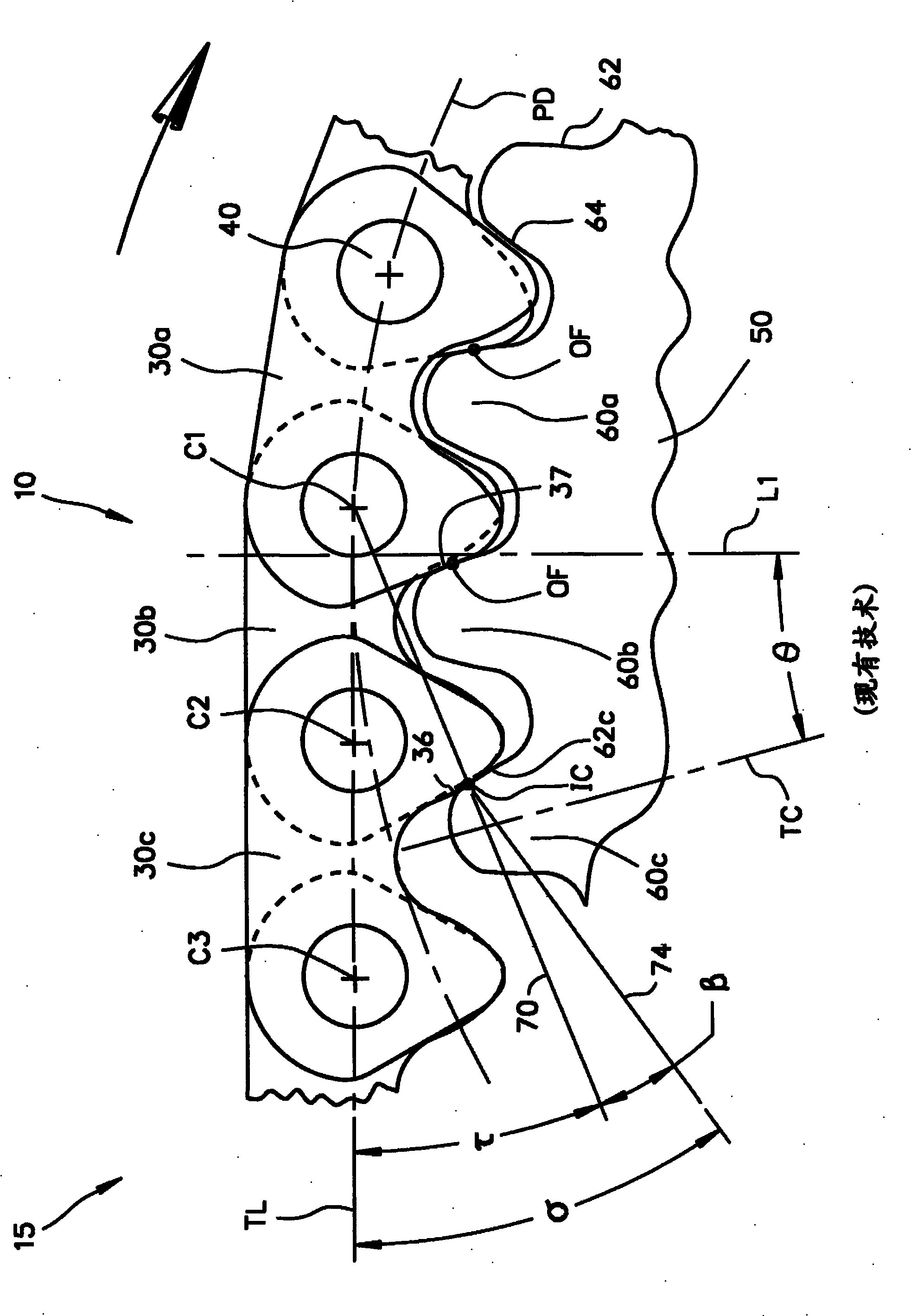
An inverted tooth chain drive system defines a meshing contact angle Tau (tau) between the tangent line TL and an initial contact reference line that passes through a controlling pin center and the initial contact location. A link plate entrance angle Beta (beta) is defined between the initial contact reference line and an inside flank reference line that passes through an arc center of the inside flank radius and the initial contact location. A meshing impact angle Sigma (sigma) is defined between the tangent line and the inside flank reference line such that sigma = tau + beta, wherein beta < 9 DEG and sigma <= 31 DEG . The pressure angle of the sprocket tooth can be adjusted and the chain optimized such that beta <= 7 DEG and sigma <= 31 DEG. The system thus provides a reduction of the link impact force FL and the resultant impact energy E. The inverted tooth chain, itself, defines a pitch P and an inside flank projection Lamda ( lamda ) such that 0.007 x P <= lamda <= 0.017 x P when said chain is pulled straight. The outside flanks include a chamfer to ensure that initial contact between the chain and sprocket is always on the leading inside flanks of the chain.

Description

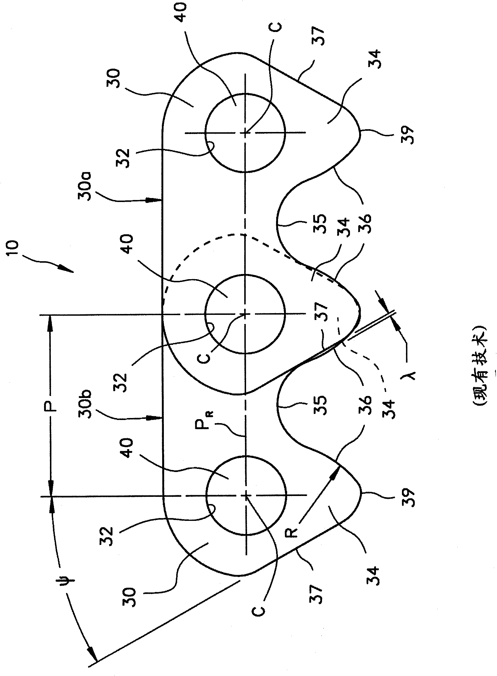
[0001] Cross References to Related Applications [0002] This application claims priority to and benefit from U.S. Provisional Application Serial No. 61 / 095,393 filed September 9, 2008 (09 / 09 / 2008), and all of the earlier provisional application No. 6I / 095,393 The disclosure is expressly incorporated into this specification by reference. Background technique [0003] Inverted tooth chains 10 have long been used in automation applications to transmit power and motion between shafts, and as figure 1 As shown, it is generally constructed as an endless chain having interleaved (interleaved) rows or rows 30a, 30b, etc., of link plates 30, each link plate having a pair of teeth 34 having outer sides 37 and inside side 36, forming a crotch 35 between the teeth; and, each link plate has two holes 32 aligned on the link row to receive connecting pins 40 (i.e. round pins, rocker joints, etc.) to The rows are pivotally coupled, and the teeth of the sprocket can be engaged on either the...

Claims


Application Information

Patent Timeline
Patent Type & Authority Applications(China)
IPC IPC(8): F16G13/04F16H7/06
CPCF16H7/06F16G13/04
Inventor 詹姆斯·D··杨达伦·J··斯图尔特
Owner CLOYES GEAR & PRODS INC
Learn More