
Retroreflective articles having microcubes, and tools and methods for forming microcubes

a technology of retroreflective elements and retroreflective objects, which is applied in the direction of instruments, other domestic objects, transportation and packaging, etc., can solve the problems of limiting the percent active aperture to less than 100%, reducing the size of the microcube, and reducing the application of known optical principles. , to achieve the effect of increasing the active apertur

Inactive Publication Date: 2008-08-12
AVERY DENNISON CORP
View PDF91 Cites 8 Cited by
  • Summary
  • Abstract
  • Description
  • Claims
  • Application Information

AI Technical Summary

Benefits of technology

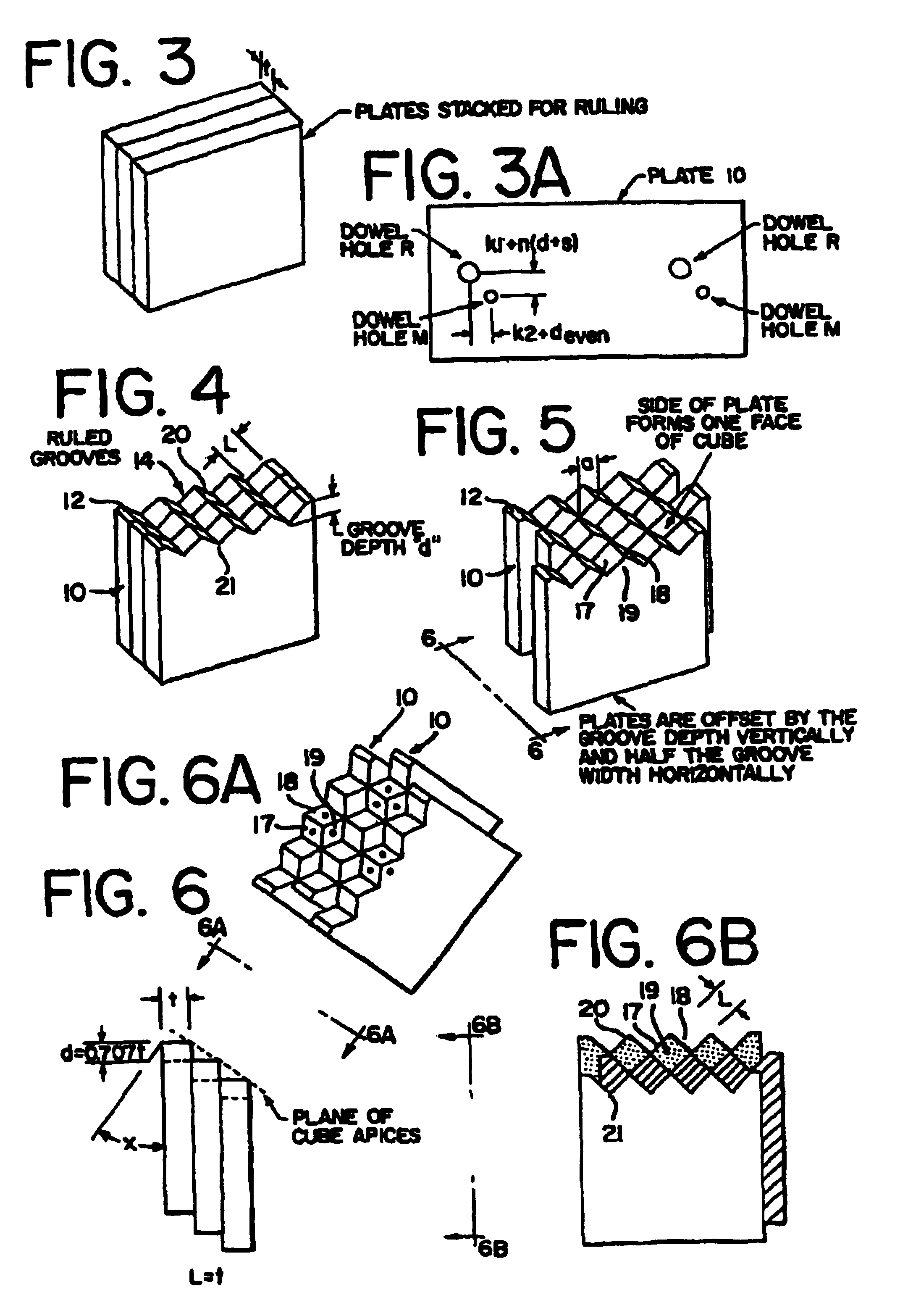
The invention is about a method for making a tool with a pattern of microcubes for making a retroreflective article. The method involves using plates with micro-sized thickness "t" and cutting them with a cutting tool to create a pattern of microcubes. The plates can be stacked and offset to create two superimposed arrays of hexagonal or rectangular cube corners. The use of hexagonal or rectangular microcubes increases the active aperture of the article. The invention provides a versatile method for making a tool for making a retroreflective article.

Problems solved by technology

While these retroreflective optic design principles are well-known in the cube corner art, in more recent years some have attempted to patent them again in microcube sheeting technology, apparently because those persons either did not know what was done in prior macrocube technology, or chose either to ignore or to limit the applicability of the prior art teachings when applied to microcube retroreflective sheeting.
This limitation is a result of the microcube dimensions being smaller than the dimensions obtainable by the cutting, polishing and lapping techniques used in the pin making art.
The need to use traditional ruling techniques has inhibited the application of known optical principles to microcubes, and has, with one exception, further generally limited percent active aperture to less than 100%.
However, all triangular cubes, while providing adequate retroreflectance, suffer the known disadvantage that inherently by their geometry no more than 66% of their area can be retroreflective for any particular incidence angle.
However, the disclosed arrays have cubes of greatly different heights (which may pose manufacturing problems) and greatly varying aperture size (affecting diffraction and impacting on retroreflectivity).
The very nature of forming these cubes by intersecting ruled grooves parallel to a single plane inherently limits the results which can be obtained.
Also unlike triangular microcubes, however, hexagonal and rectangular microcubes are not defined by continuous straight lines that extend along a planar surface, and therefore cannot be ruled with intersecting sets of parallel lines all parallel to a common plane.
Thus, with the sole exception of the rectangular cubes disclosed in U.S. Pat. Nos. 4,349,598 and 4,895,428 (wherein one of the active cube faces is perpendicular to the reflector front surface) it is not possible to cut or rule a master containing all hexagonal or all rectangular microcubes by ruling straight lines in a single flat surface.
Moreover, because of the geometric limitations inherent in ruling the cubes for the U.S. Pat. No. 4,349,598 and U.S. Pat. No. 4,895,428 patents, the cube structures disclosed therein are not useful where the primary light source will generally be at a near-zero incidence angle, such as in highway sign sheeting.
However, this technique was disclosed decades earlier by applicants' assignee's founder and was stated to be an unsatisfactory technique for tooling retroreflectors, see U.S. Pat. No. 1,591,572 (FIG. 16, p.
Heretoforer, the above-described “stacked plates” method of forming macrocubes was not of practical interest for producing molds for retroreflective products on a commercial scale.
Secondly, as observed in U.S. Pat. No. 1,591,572, by using conventional machining and polishing techniques, it was not possible to cut and polish inside-intersecting faces with the precise angular tolerances and sharp edges achievable with the pin technique.
In particular, any irregularities in the cube surfaces as might be caused by either the cutting operation or the polishing operation could disadvantageously increase the divergence of the retroreflected light and thus diminish the effective retroreflectivity of the cubes so formed.
This recognized difficulty in polishing grooved internal angles is highly exacerbated with microcubes because the area that cannot be polished flat is a relatively greater percentage of the resulting cube face area.

Method used


Image

  • Retroreflective articles having microcubes, and tools and methods for forming microcubes
  • Retroreflective articles having microcubes, and tools and methods for forming microcubes
  • Retroreflective articles having microcubes, and tools and methods for forming microcubes

Examples


example 1

Retroreflectors For Increased Entrance Angularity

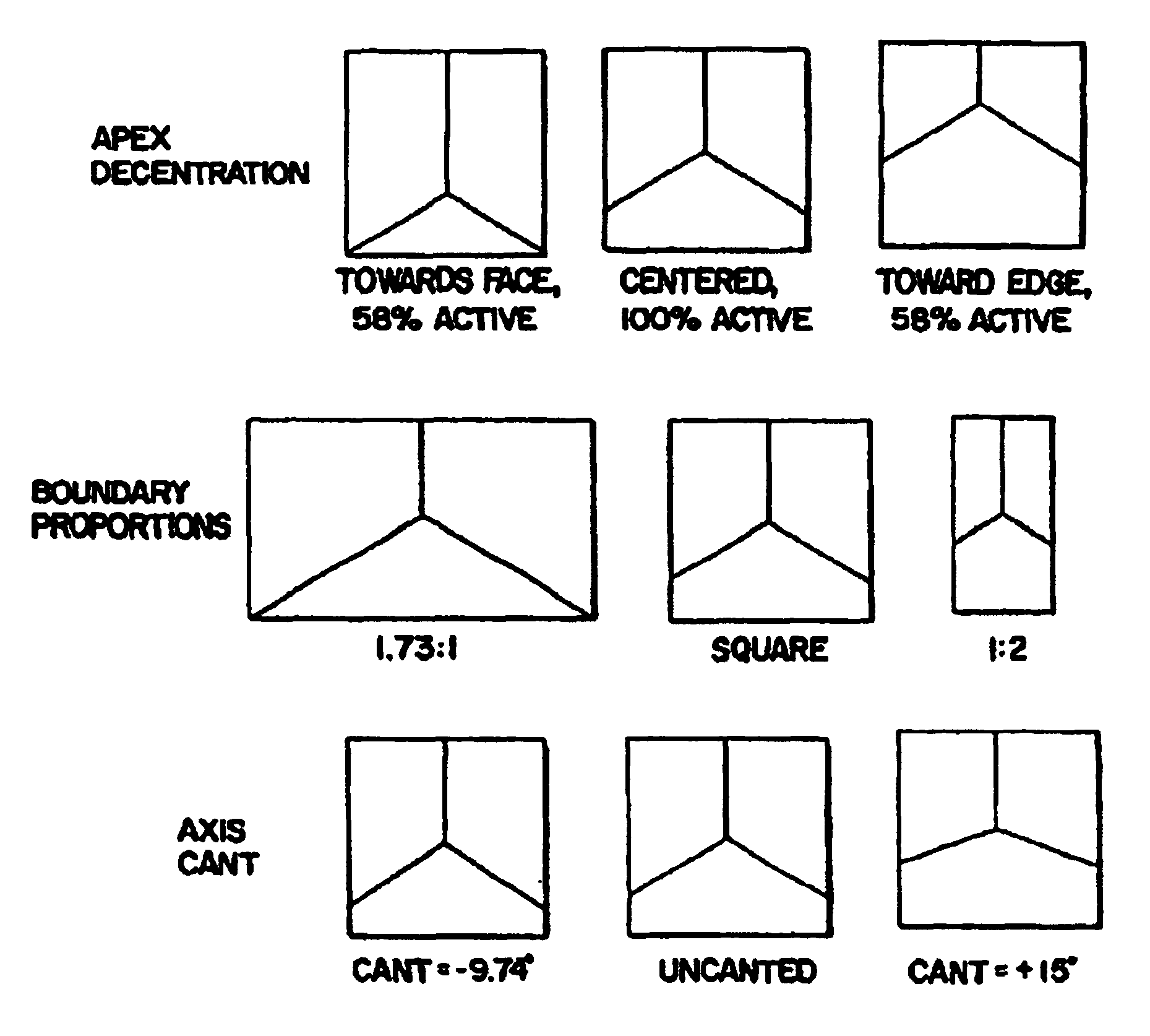
[0225]To increase the entrance angularity of the cubes as described in patents U.S. Pat. Nos. 3,541,606, 3,873,184 and U.S. Pat. No. 3,923,378 issued to the same assignee and incorporated herein by reference, the s / t=0, d / t=0.707 solution shown in FIG. 6 might be superseded by an s / t=0.45; d / t=0.55 solution as shown in FIG. 13, for which the cube axis tilt is −9.74° to the front surface of the array and the percent active aperture is 72.5% at 0° incidence angle and 100% at 19.6° incidence angle. (Throughout this example, the entrance plane is assumed to be aligned with the symmetry plane of the cube corners, and the refractive index is assumed to be 1.59.) However, if the hexagon arrays are paired for each cube favorably oriented for 19.6° incidence angle, there is also its mirror image having only 45% effective aperture for that same incident light; the paired array therefore averages 72.5% for light incident at an angle of 19.6°, wh...

example 2

Retroreflectors For Large Incidence Angles, Such As For Pavement Markers

[0231]Example 2 is quite different. The method of Example 2 is intended to maximize the retroreflectance through a relatively smaller range of entrance angles about an axis (the principal incident ray) which is not normal to the face of the retroreflector. For example, a raised retroreflective lane marker mounted on a road may have its front surface tilted back 60° from a plane perpendicular to the plane of the pavement. A light ray from the headlight of an approaching vehicle, being substantially parallel to the pavement, becomes incident on the face of the retroreflector at an angle to the normal of 60° and is refracted (in acrylic) to an angle to the normal of 35.5°. For purposes of discussion, the ray parallel to the pavement surface and to the centerline of the road will be called the principal incident ray of optical axis and the ray within the marker after reflection at the front surface will be called th...

example 3

Retroreflectors With Increased Divergence

[0239]The divergence of the retroreflected beam (i.e., the observation angularity) can be varied in one plane or in multiple planes by changing the dihedral angles between either two or three faces as taught in U.S. Pat. No. 3,833,285 also to the same assignee and incorporated herein by reference and / or by changing the size of the cube, which affects diffraction.

[0240]The dihedral angle can be changed by making the groove angle greater or less than 90° and / or by tilting the stack of plates 10 slightly off the perpendicular to the cutting plane, as illustrated by angle “b” in FIG. 11, before the grooves are cut. The groove angle can be varied by changing the angle “C” of the diamond tool (FIG. 7A) or by adjusting the angle “e” of the diamond tool (FIG. 8B) with respect to the perpendicular to the surface being ruled, in accordance with Equation A, previously stated.

[0241]The tilt angle “e” of the cutting tool can be held constant for all groov...


PUM

PropertyMeasurementUnit
areaaaaaaaaaaa
areaaaaaaaaaaa
areaaaaaaaaaaa

Abstract

A method for tooling a pattern of retroreflective microcubes, which pattern can be subdivided into smaller increments within which there are straight line tooling paths, none of which pass through an otherwise solid part of the incremental pattern. The tooling paths within the various increments need not be parallel to a common plane.Various adaptions of the method enable the tooling of a number of specific microcube shapes and for modifying such optical properties of the microcubes as entrance angularity, incidence angularity, orientation angularity, observation angularity, percent active aperture and retroreflectance. Specific techniques govern the pre-selection of cube parameters such as cube axis cant, cube apex decentration, and cube boundary proportions, which parameters can be adjusted independently of each other. Designs tooled by the method can have 100% active aperture at near zero degrees entrance angle.The method involves providing a plurality of plates of micro thickness, each plate having at least one end comprised of a material that can be tooled with polished surfaces by means of an appropriate tool, tooling on said end of each plate an increment of the pattern, and assembling the plates together in various ways to form a master.Retroreflective articles made by means of this technique are expected to provide superior performance when used in pavement markers, highway signs and other applications.

Description

[0001]This is a divisional of copending application(s) U.S. Ser. No. 08 / 655,595 filed on May 30, 1996 now U.S. Pat. No. 6,015,214.BACKGROUND OF THE INVENTION[0002]This invention relates to tools for making microcube retroreflective elements for use in manufacturing retroreflective articles, and in particular, retroreflective sheeting; to articles and sheeting having microcubes; and to methods of making such tools and articles; This invention further relates to tools, articles, and methods wherein said microcubes may have boundary shapes other than triangular.[0003]Microcube retroreflective sheeting is now well-known as a material for making reflective highway signs, safety reflectors, reflective vests and other garments, and other safety-related items. Such retroreflective sheeting typically comprises a layer of a clear resin, such as for example, an acrylic or polycarbonate or vinyl, having a smooth front surface and a plurality of retroreflective microcube elements on the reverse ...

Claims


Application Information

Patent Timeline
Patent Type & Authority Patents(United States)
IPC IPC(8): G02B5/124B32B3/00B29C33/30B29C33/38B29C33/42B29C39/00B29C43/00B29D11/00G02B5/122
CPCB29C33/42B29D11/00605G02B5/124B29C33/301B29C33/3842B29C39/00Y10T428/24612B29C2059/023B29L2011/0091B29C43/00Y10T428/249921
Inventor HEENAN, SIDNEY A.COMAN, LIVIU A.COUZIN, DENNIS I.
Owner AVERY DENNISON CORP
Learn More