Electronic cam control system and method of programmable logic controller

An electronic cam and programming logic technology, applied in the field of automation, can solve the problems of inapplicability to high-speed production equipment, the impact of PLC scan cycle, and high costs, to improve system accuracy and signal response capabilities, to ensure high-speed response capabilities, and the right timing. unmistakable effect

Active Publication Date: 2014-03-26
广州市兴世电子有限公司
View PDF3 Cites 8 Cited by
  • Summary
  • Abstract
  • Description
  • Claims
  • Application Information

AI Technical Summary

Problems solved by technology

[0003] Recently, many companies have produced special electronic cam controllers as a flexible intelligent module of PLC. However, using PLC to read the position of the absolute encoder and output the signal after calculation and comparison requires a relatively large amount of time. Multiple PLC resources, due to the signal delay of the PLC input point and the impact of the PLC scan cycle (especiall

Method used


Image

  • Electronic cam control system and method of programmable logic controller
  • Electronic cam control system and method of programmable logic controller
  • Electronic cam control system and method of programmable logic controller

Examples


Embodiment Construction

[0048] The following will clearly and completely describe the technical solutions in the embodiments of the present invention with reference to the accompanying drawings in the embodiments of the present invention. Obviously, the described embodiments are only some, not all, embodiments of the present invention. Based on the embodiments of the present invention, all other embodiments obtained by persons of ordinary skill in the art without creative efforts fall within the protection scope of the present invention.

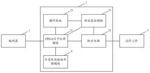
[0049] The embodiment of the present invention provides an electronic cam control system of a programmable logic controller, such as figure 1 As shown, it includes an encoder 1, a controller 2 and an action element 3, the encoder is used to obtain the position information of the mechanical shaft, and the controller 2 processes the signal sent by the encoder 1 to control the action element 3 actions.

[0050] In this embodiment, the encoder is a 1024 / 2048 line ABZ ...


PUM


Abstract

The invention discloses an electronic cam control system of a programmable logic controller. The electronic cam control system comprises an encoder and a controller, and the controller comprises an FPGA signal processing module and an output circuit. The FPGA signal processing module comprises an encoder position decoding unit, a CPU and a signal comparison unit, wherein the encoder position decoding unit is used for decoding an encoded position data signal sent by the encoder, obtaining current position data of a mechanical shaft and calculating the current rotating speed of the mechanical shaft; the CPU is used for receiving the current rotating speed of the mechanical shaft, and calculating ON/OFF parameters of an actual action based on the current rotating speed of the mechanical shaft and based on ON/OFF parameters and entrance angle compensating parameters which are set by users; the signal comparison unit is used for comparing the ON/OFF parameters, output by the CPU, of the actual action and the current position data, output by the encoder position decoding unit, of the mechanical shaft, and if the current position data of the mechanical shaft are within the range of the ON/OFF parameters of the actual action, an on/off signal is sent to a corresponding action element so as to control actions of the action element.

Description

technical field [0001] The invention relates to the field of automation, in particular to an electronic cam control system and method of a programmable logic controller. Background technique [0002] Conventionally, a mechanical cam was used, and a sensor was used to detect the position of the cam and output a signal. This method is difficult to adjust the mechanical cam, and the cam position cannot be modified while the equipment is running. The sensor signal is delayed and cannot be compensated for mechanical delays at high speeds. Moreover, after the design of the mechanical cam is completed, the action of its follower is determined. If the action law is to be changed, the cam must be redesigned and installed. In addition, the number of mechanical cams is also limited by the size and complexity of the machine. If it is required to drive the actuator at the corresponding position to generate action and monitor it while performing multi-station mechanical transmission, f...

Claims


Application Information

Patent Timeline
IPC IPC(8): G05B19/06
Inventor 林颖宗赵辉球
Owner 广州市兴世电子有限公司
Why Eureka
Try Eureka