High-voltage transformer

A technology for high-voltage transformers and transformer cores, applied in the field of high-voltage transformers, can solve the problems of increasing the weight of dry-type transformers, and achieve the effect of weight saving

Active Publication Date: 2011-08-03
B2 ELECTRONICS
View PDF3 Cites 0 Cited by
  • Summary
  • Abstract
  • Description
  • Claims
  • Application Information

AI Technical Summary

Problems solved by technology

The use of thicker wire for the secondary coil also disadvantageously results in increased weight of the dry-type transformer

Method used


Image

  • High-voltage transformer
  • High-voltage transformer
  • High-voltage transformer

Examples


Embodiment Construction

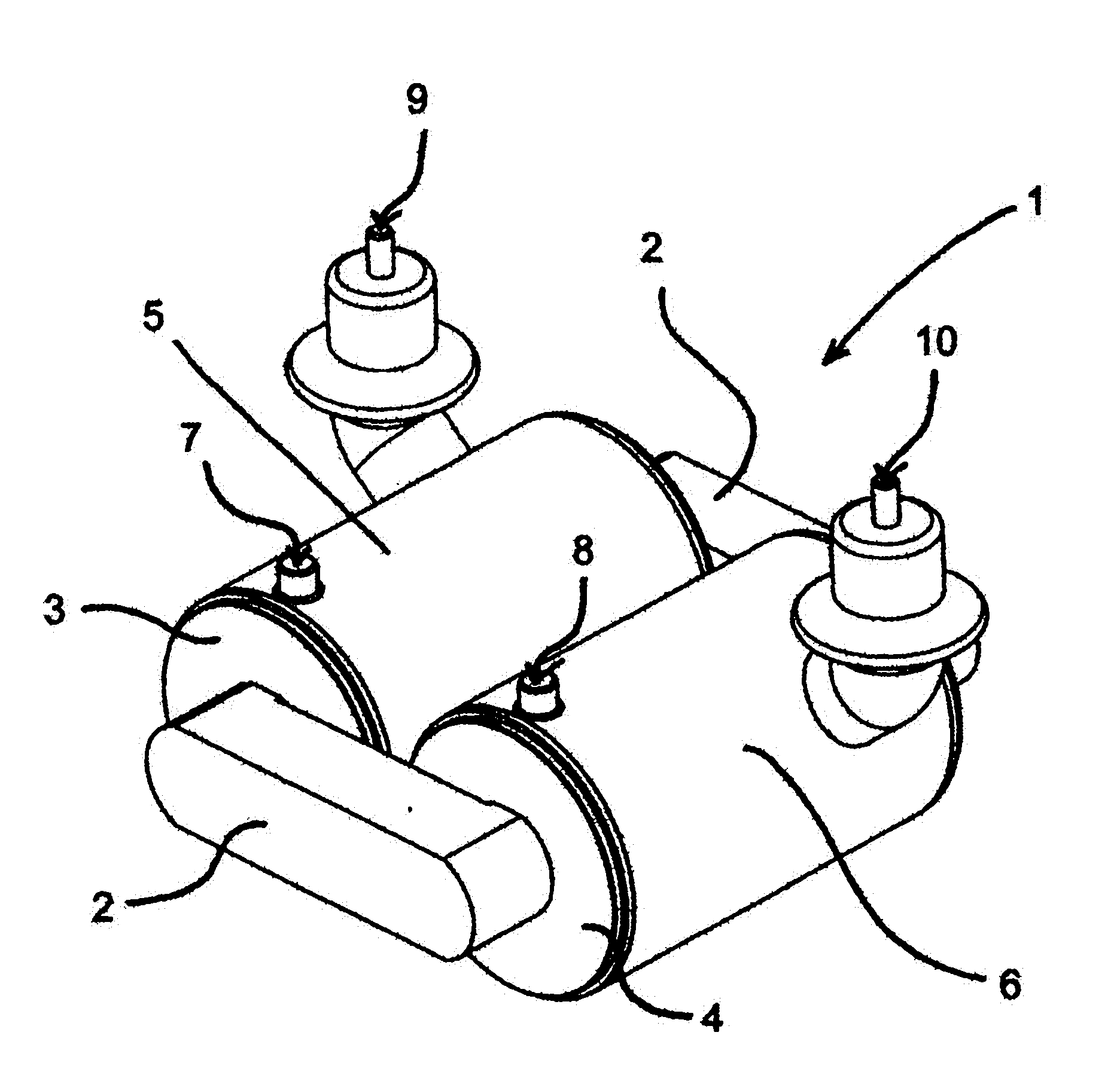
[0042] exist figure 1 The high-voltage transformer 1 shown in FIG. 2 comprises a ferromagnetic transformer core 2 around which two primary windings 3 , 4 (designed as disk windings and separately insulated) are currently wound on different arms.

[0043] in addition, figure 1 Shown are two insulating housings 5, 6 each enclosing one arm of the transformer core 2, wherein a low-voltage-side connection 7, 8 and Connectors 9, 10 on the high pressure side. All connections 7 , 8 , 9 , 10 are designed in such a way that they make contact with the relevant end of the secondary winding or that corresponding contacting takes place through them.

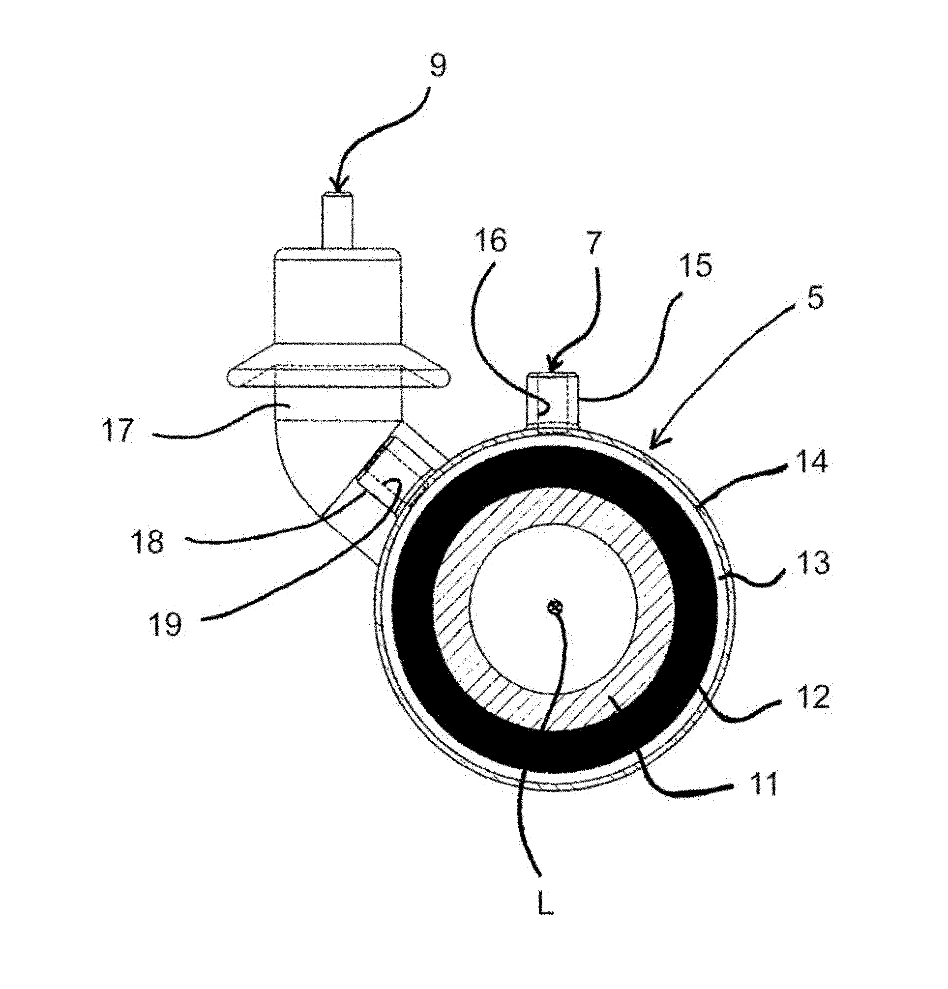
[0044] figure 2 The shown sectional view is perpendicular to the longitudinal axis L of the insulating housing 5 and, for reasons of clarity, both through the connection 7 on the low-voltage side and through the connection 9 on the high-voltage side, so that the exact structure of the insulating housing 5 can be drawn , which has the same...


PUM

PropertyMeasurementUnit
diameteraaaaaaaaaa
thicknessaaaaaaaaaa

Abstract

In a high-voltage transformer (1) for providing an alternating voltage in the kV range, comprising at least one secondary winding (12), which is wound on a coil carrying body (11) surrounding a transformer core (2), an insulation housing (5, 6) encapsulating the secondary winding (12) is provided to electrically insulate the secondary winding (12). Said insulation housing is walled by the coil carrying body (11) carrying the secondary winding (12) and by an enveloping body (14) made of plastic and enveloping the secondary winding (12) so that an annular gap (13) is formed, wherein the annular gap (13) between the secondary winding (12) and the enveloping body (14) is filled with an insulating fluid. The annular gap (13) filled with insulating fluid has a gap width of less than or equal to 20 mm viewed in the cross-section, and the enveloping body (14) has a wall thickness of less than or equal to 20 mm, wherein the plastic is polypropylene, and a separate expansion volume is not provided for the insulating fluid.

Description

technical field [0001] The invention relates to a high-voltage transformer for supplying alternating voltages in the kilovolt range, with at least one secondary winding wound on a coil carrier surrounding a transformer core. Background technique [0002] Such high-voltage transformers are sufficiently known from the prior art. Such a high-voltage transformer is usually a component of a (possibly movable) testing or measuring device, in which the high voltage tapped off at least one secondary winding is used as a test voltage for the component to be tested or for other measuring purposes. [0003] In this case, an input alternating voltage is applied to the primary winding of the transformer, which surrounds, for example, a ferromagnetic transformer core, for example composed of iron or iron laminations. The magnetic field induced in the transformer core thus induces in at least one secondary winding a secondary voltage whose amplitude is essentially dependent on the ratio o...

Claims


Application Information

Patent Timeline
Patent Type & Authority Applications(China)
IPC IPC(8): H01F27/32
CPCH01F27/321
Inventor 鲁道夫.布兰克斯蒂芬.巴尔多夫
Owner B2 ELECTRONICS
Why Eureka
Try Eureka