
Ceramic heater

A ceramic heater and ceramic technology, applied in the direction of ohmic resistance heating, heating element materials, electric heating devices, etc., can solve the problems of ceramic substrate cracking and unbearable, so as to prevent heater cracking, improve efficiency, and shorten heating time. Effect

Active Publication Date: 2011-08-03
KYOCERA CORP
View PDF1 Cites 0 Cited by
  • Summary
  • Abstract
  • Description
  • Claims
  • Application Information

AI Technical Summary

Problems solved by technology

Furthermore, a ceramic heater that produces a large temperature distribution during heating cannot withstand the thermal stress caused by the temperature distribution when it is repeatedly used, and sometimes causes the ceramic substrate to crack

Method used


Image

  • Ceramic heater
  • Ceramic heater
  • Ceramic heater

Examples


Embodiment

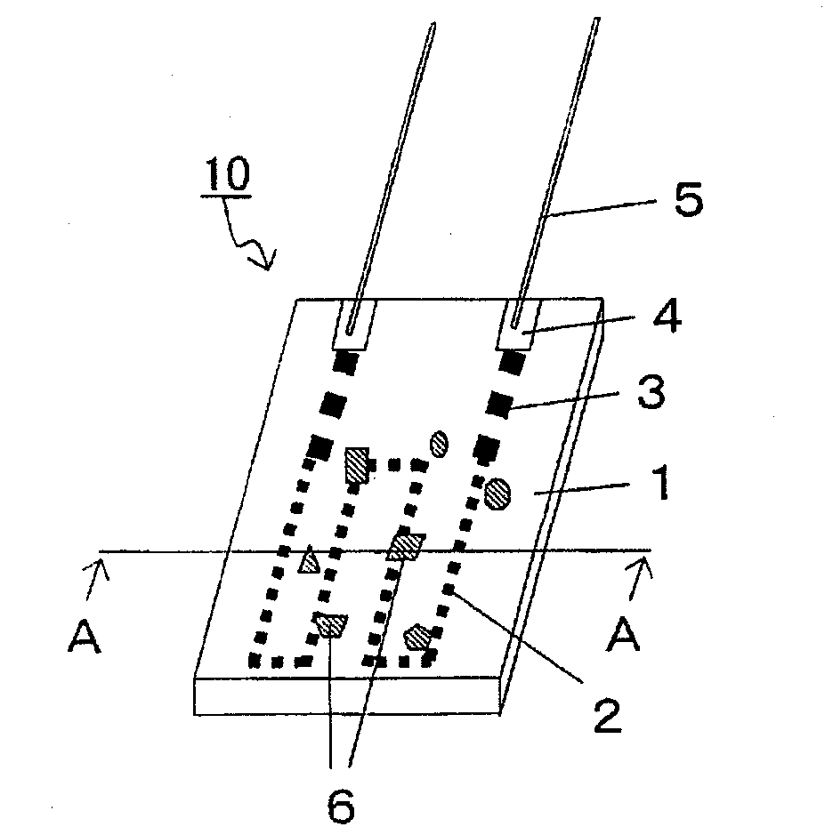
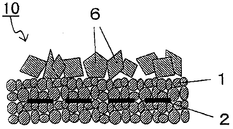
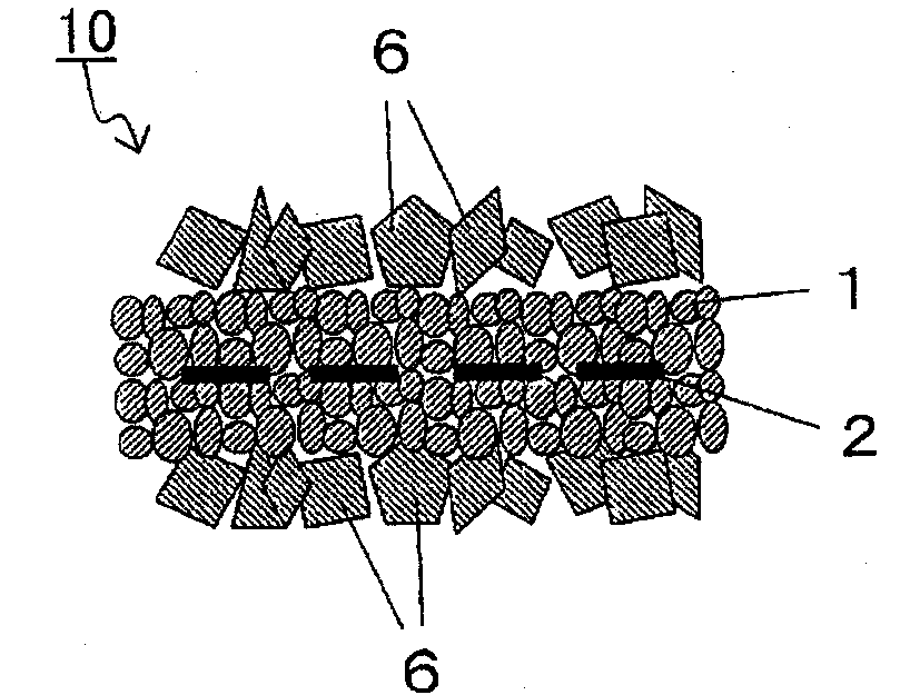
[0060] made as follows Figure 1 ~ Figure 3 A ceramic heater 10 of the present invention is shown.

[0061] First, make the following Al 2 o 3 as the main component, SiO 2 , CaO, MgO, ZrO 2A ceramic green sheet prepared so that the total amount is within 10% by mass. Then, on the surface of the ceramic green sheet, the heating element 2 , the lead portion 3 , and a conductive paste mainly composed of W serving as the electrode pad 4 were printed in a pattern by screen printing. Ceramic green sheets printed with these patterns and non-printed ceramic green sheets of the same material and shape were coated and laminated with a lamination liquid in which ceramics of the same composition were dispersed to obtain a plate-like molded body.

[0062] Next, a plurality of particles 6 are printed and applied to the main surface of the stacked plate-like molded body by the screen printing method. In addition, for the sample in which the particles 6 were fixed to both main surfaces,...


PUM


Abstract

Disclosed is a ceramic heater having excellent heat transfer characteristics which affords a reduction in the heating time of an object to be heated and a reduction in the temperature distribution across the surface thereof. A ceramic heater (10) is constituted of an exothermic body (2) provided within a plate-shaped ceramic body (1), and a large number of inorganic particles (6) fixed to the main surface of the ceramic body (1). The specific surface area of the main surface of the ceramic heater (10) is increased by the large number of particles (6) fixed thereto and the heat transfer efficiency to the object to be heated is improved, and the heating time can be reduced. In addition, the temperature distribution across the main surface of the ceramic body (1) can be reduced.

Description

technical field [0001] The present invention relates to a ceramic heater used for curling irons, heaters for heating water, oxygen sensors, air-fuel ratio sensors, spark plugs and the like. Background technique [0002] Conventionally, heaters for curling irons, heaters for water heating, fuel liquefaction, vaporization, etc., and heaters for oxygen sensors, air-fuel ratio sensors, and spark plugs have all used ceramic heaters. As ceramic heaters used for these purposes, for example, there are known: Figure 6 As shown, a heating resistor 102 is embedded in a ceramic substrate 101, and a lead member 105 is connected to a lead member 105 electrically connected to an end portion of the heating resistor 102 and an external electrode (electrode pad) 104 via solder. device 110 (for example, refer to Patent Document 1). here, Figure 6 It is a perspective view showing an example of a conventional ceramic heater. [0003] Patent Document 1: (Japanese) Unexamined Patent Publicatio...

Claims


Application Information

Patent Timeline
Patent Type & Authority Applications(China)
IPC IPC(8): H05B3/12H05B3/14H05B3/18
CPCH05B3/141H05B3/12H05B3/14H05B3/18
Inventor 长迫龙一
Owner KYOCERA CORP
Learn More