
Installation structure for cam shaft and timing gear

A timing gear and installation structure technology, applied in the direction of belt/chain/gear, valve device, hoisting device, etc., can solve the problems of stress concentration of positioning keys, large torque of bolts, scrapped engine, etc. The effect of loosening and prolonging the service life

Active Publication Date: 2011-08-10
CHERY AUTOMOBILE CO LTD
View PDF4 Cites 7 Cited by
  • Summary
  • Abstract
  • Description
  • Claims
  • Application Information

AI Technical Summary

Problems solved by technology

At present, the combination of the timing gear and the camshaft in the engine is through a positioning key, that is, a separate positioning key is arranged on the front end of the camshaft or the timing gear. Together, but this type is positioned by a separate key, which is prone to stress concentration around the positioning key, and may even cause the positioning key to break
In addition, there are some engines, there is no positioning pin between the timing gear and the camshaft, and the bolts are directly used for fixed assembly, which is more convenient for assembly, but the bolt tightening requires a large torque. The bolts of the engine may loosen, the timing may deviate, and the piston tops the valve, causing the engine to be scrapped.

Method used


Image

  • Installation structure for cam shaft and timing gear
  • Installation structure for cam shaft and timing gear
  • Installation structure for cam shaft and timing gear

Examples


Embodiment 1

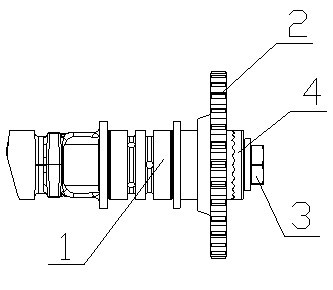
[0019] Such as figure 1 As shown, the camshaft timing gear installation structure of the present invention includes a camshaft 1, a timing gear 2, a bolt 3, and a gasket 4. Between timing gear 2 and bolt 3.

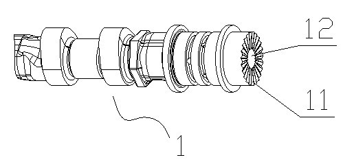
[0020] Such as figure 2 As shown, the surface of one end of the camshaft 1 is provided with a radial spline 11 , and the center of the end is provided with an axial screw hole 12 for installing the bolt 3 .

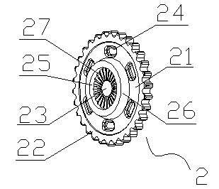
[0021] Such as image 3 , 4 , 5, the timing gear 2 is composed of three parts: a wheel disc 21, a gear tooth 22 and a shaft hole 23, and the outer periphery of the wheel disc 21 is provided with gear teeth 22, which are used to cooperate with the timing chain, wherein the number of gear teeth 22 It can be arranged according to actual needs. The wheel disc 21 between the gear teeth 22 and the shaft hole 23 is concave, and there are a plurality of arc-shaped weight-reducing holes 24 on the wheel disc cloth, and the weight-reducing holes 24 are evenly distributed ...


PUM


Abstract

The invention aims to provide a durable installation structure for a cam shaft and a timing gear. The structure can position accurately and is convenient to install. The installation structure for the cam shaft and the timing gear comprises the cam shaft, the timing gear and a bolt, and is characterized in that the surface of one end part of the cam shaft is provided with radial splines; the center of the end part is provided with an axial screw hole for installing the bolt; the middle of the timing gear is provided with shaft holes, one side of the timing gear is provided with radial splines which are matched with and engaged with the splines of the cam shaft, the timing gear is fixed at the end part of the cam shaft in a tightening mode through the bolt; and the splines of the timing gear are in fit connection with the splines of the cam shaft, thus the installation is convenient and the work efficiency is improved. By using the installation structure, not only can the timing gear be positioned, but also stress generated when the timing gear and the cam shaft rotate can be dispersed, thereby eliminating stress concentration and prolonging service life.

Description

technical field [0001] The invention belongs to the technical field of automobile manufacturing, and in particular relates to a camshaft timing gear installation structure of an automobile engine. Background technique [0002] Timing gears (camshaft gears and crankshaft timing gears) are a set of precision gears used by the engine to control the timing and ignition of the engine. Whether the timing gear can be installed on the camshaft according to the set position is the key to whether the timing and ignition are accurate. At present, the combination of the timing gear and the camshaft in the engine is through a positioning key, that is, a separate positioning key is arranged on the front end of the camshaft or the timing gear. Together, but this type is positioned by a separate key, which is prone to stress concentration around the positioning key, and may even cause the positioning key to break. In addition, there are some engines, there is no positioning pin between th...

Claims


Application Information

Patent Timeline
Patent Type & Authority Applications(China)
IPC IPC(8): F01L1/047F01L1/46F16H55/17
Inventor 霍英贤
Owner CHERY AUTOMOBILE CO LTD
Learn More