
Discharging device and tank body with same

A technology for unloading devices and tanks, which is applied to fixed-capacity gas storage tanks, container discharge methods, gas/liquid distribution and storage, etc., and can solve problems such as difficulty in liquid intake, reduced tank utilization, and economic losses

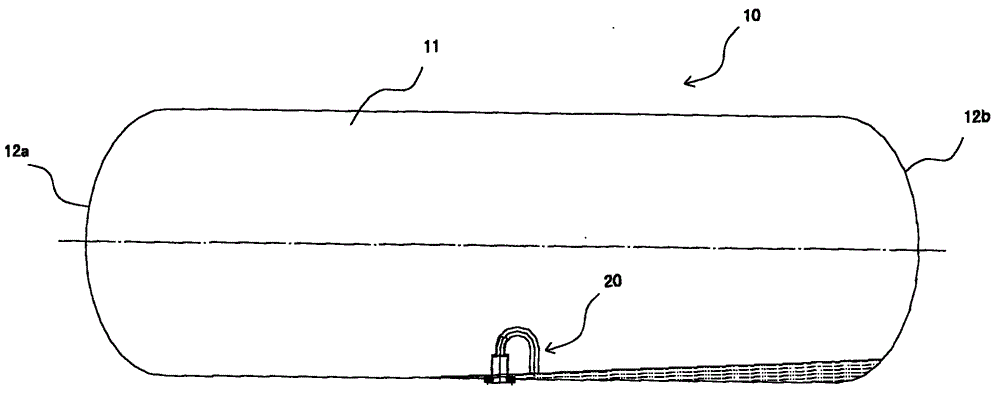
Active Publication Date: 2012-10-10
NANTONG CIMC ENERGY EQUIP CO LTD
View PDF0 Cites 0 Cited by
  • Summary
  • Abstract
  • Description
  • Claims
  • Application Information

AI Technical Summary

Problems solved by technology

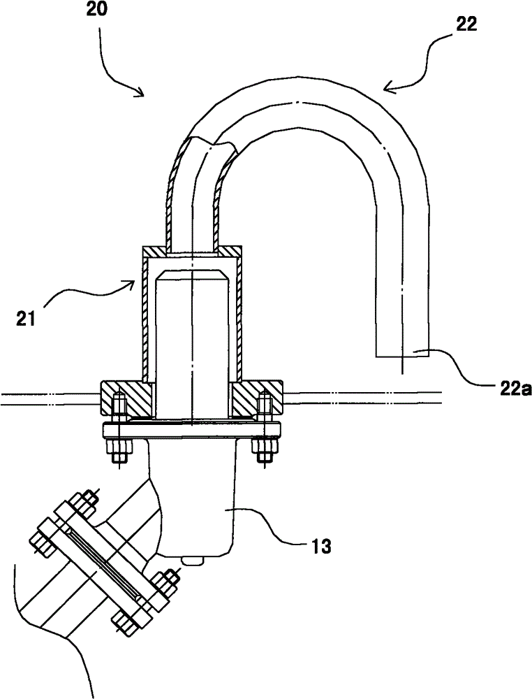
However, because the length of the discharge part 22 is relatively short, and its angle of inclination is too vertical, the opening end 22a of the discharge part 22 is positioned above the liquid level of the residual liquefied gas, which makes it difficult to enter the opening end 22a. As a result, the liquefied gas in the tank body 10 cannot be completely discharged, resulting in a reduction in the utilization rate of the internal volume of the tank body for transporting tank trucks, resulting in unnecessary economic losses

Method used


Image

  • Discharging device and tank body with same
  • Discharging device and tank body with same
  • Discharging device and tank body with same

Examples


Embodiment Construction

[0025] In the following, the present invention will be specifically described through exemplary embodiments. It is to be understood, however, that elements, structures and characteristics described in one embodiment may be beneficially incorporated into other embodiments without further recitation.

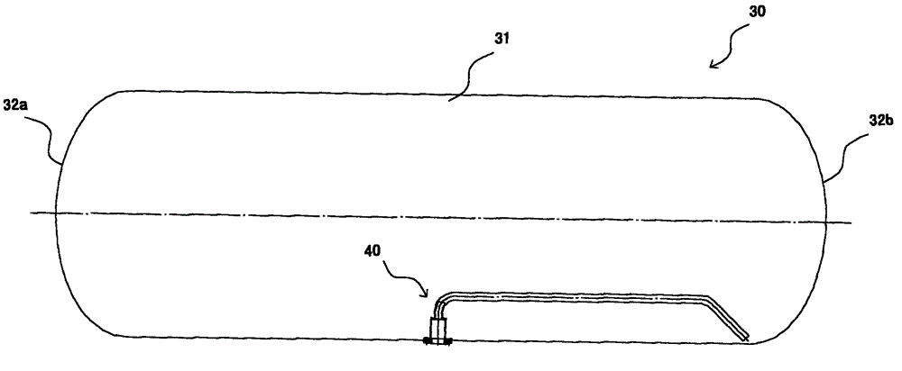
[0026] image 3 The structure of the tank body 30 according to an embodiment of the present invention is shown. The tank body 30 includes a cylinder body 31 and caps 32a, 32b provided at both ends of the cylinder body 31 .

[0027] Usually, in order to facilitate the discharge of the liquefied gas inside the tank, a discharge valve 13 is also provided at the bottom of the cylinder 31 (see Figure 4 ), in order to prevent the residual moisture in the tank body 30 from freezing and blocking the discharge valve in winter, and to prevent debris in the tank body 30 from entering the discharge valve 13, thereby affecting the normal discharge of the tank body, the tank body 30 is also ...


PUM


Abstract

The invention discloses a discharging device which is used for being arranged on a tank body. The tank body comprises a cylinder body and an end socket. The discharging device comprises an installing part and a discharging part, wherein the installing part is connected to the bottom of the cylinder body, the discharging part comprises a first discharging part and a second discharging part, the first discharging part is provided with a bending structure and a flattening structure, the bending structure is connected to the upper end of the installing part, the flattening structure extends from one end of the bending structure, far away from the installing part, to the end socket and is parallel to the bottom of the cylinder body; and the second discharging part is communicated with the first discharging part and extends aslant from the tail end of the flattening structure to the bottom of the cylinder body, and the tail end of the second discharging part is an opening end close to the bottom of the cylinder body. The invention also discloses a tank body with the discharging device. Due to the discharging device, materials inside the tank body can be completely discharged, thus effective volume inside the tank body is increased and economic benefit is improved.

Description

technical field [0001] The invention relates to a discharge device and a tank body with the discharge device. Background technique [0002] Liquefied petroleum gas, liquefied ammonia, liquid chlorine, liquefied propylene, liquefied propane and other liquefied gases can be transported by special transport tank cars, wherein the transport tank cars are all equipped with tanks for containing liquefied gas. [0003] Such as figure 1 As shown, the tank body 10 generally includes a substantially cylindrical barrel body 11 and caps 12a, 12b located at both ends of the barrel body 11 . [0004] Usually, the bottom of the cylinder body 11 is also connected with a bottom discharge valve 13 (see figure 2 ), used to discharge the liquefied gas inside the tank body 10. In order to prevent the residual moisture at the bottom of the tank body 10 from freezing in winter, the bottom discharge valve 13 is blocked, and a discharge device 20 is also arranged at the bottom of the cylinder bo...

Claims


Application Information

Patent Timeline
Patent Type & Authority Patents(China)
IPC IPC(8): F17C7/00
Inventor 马锡山梁勋南邓明华蒋春辉
Owner NANTONG CIMC ENERGY EQUIP CO LTD
Learn More