Oil well pump capable of automatically draining oil

An oil well pump and self-draining technology, which is applied in the field of self-draining oil well pumps, can solve problems such as splashing, difficult operation, and unfavorable safety, and achieve the effects of preventing environmental pollution, avoiding external splashing, and improving safety

Active Publication Date: 2022-05-27
PETROCHINA CO LTD
View PDF8 Cites 0 Cited by
  • Summary
  • Abstract
  • Description
  • Claims
  • Application Information

AI Technical Summary

Problems solved by technology

However, a problem also arises, that is, in order to ensure the reliability of the oil well pump at work, the oil well of the large diameter oil well pump is usually not installed with a drainer, which eventually leads to the liquid in the oil pipe following the operation of the pipe string. When the coupling is unscrewed, the liquid in the oil pipe will splash outward, which is very unfavorable to the safety of the oil well operation and the environment. At the same time, operators need to operate at the wellhead, which is very unfavorable to the health of the operators.
At present, although there are many kinds of downhole oil drainers for large-diameter oil well pumps, they are difficult to adapt to the complex environment downhole, and are difficult to control and malfunction (that is, opening in advance or not opening when it needs to be opened) often happens
[0003] Aiming at the problem that the downhole oil drainer in the related technology is difficult to control and the oil drainage effect is not good, no effective solution has been given so far

Method used


Image

  • Oil well pump capable of automatically draining oil
  • Oil well pump capable of automatically draining oil
  • Oil well pump capable of automatically draining oil

Examples


Embodiment Construction

[0056] In order to have a clearer understanding of the technical features, purposes and effects of the present invention, specific embodiments of the present invention will now be described with reference to the accompanying drawings.

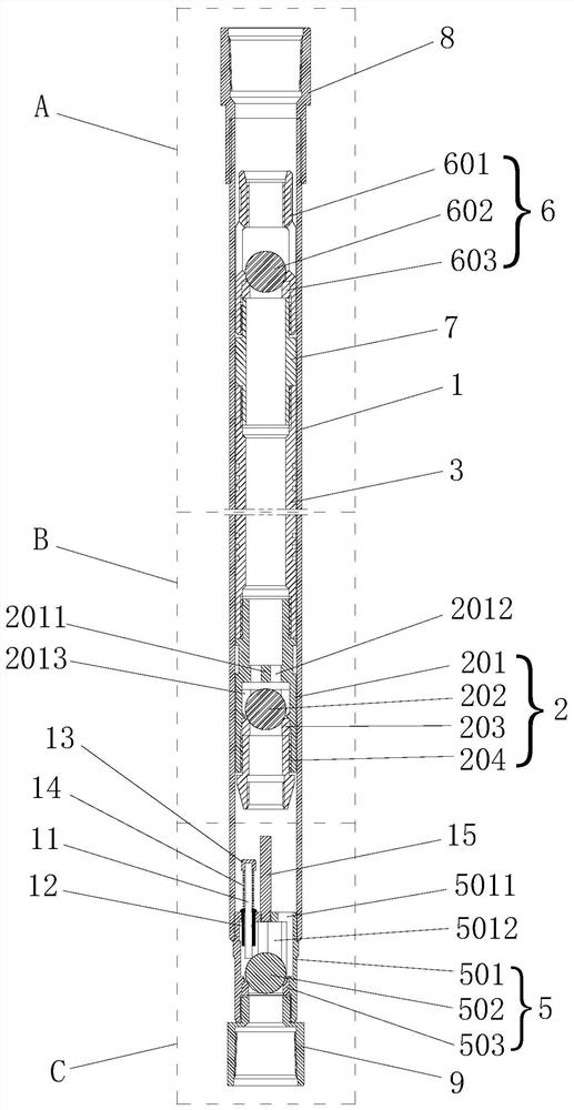
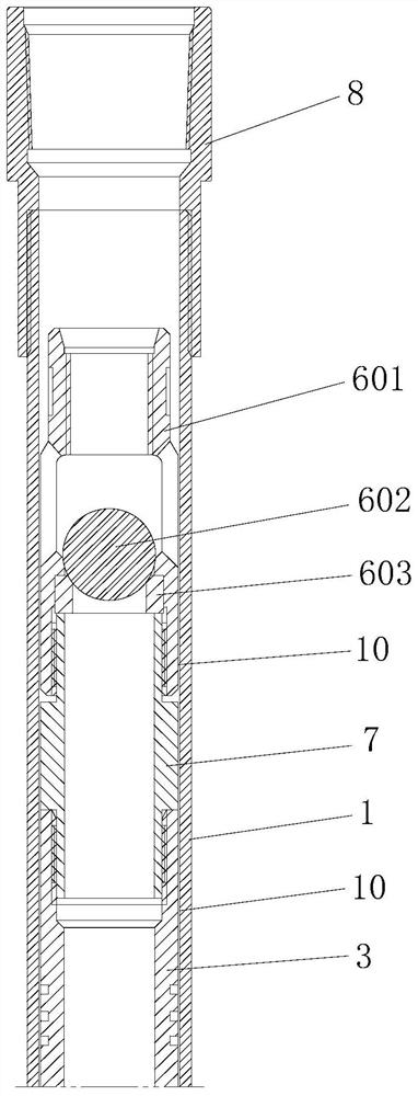
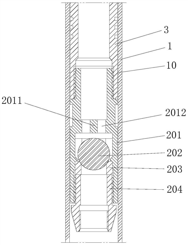
[0057] like Figure 1 to Figure 6 As shown, the present invention provides a self-draining oil well pump, which is arranged at the bottom of the sucker rod and goes down to a preset position in the wellbore with the sucker rod. The self-draining oil pump includes a pump barrel 1 and a plunger 3. Both the pump barrel 1 and the plunger 3 are cylindrical structures arranged in a vertical direction with openings at both ends, and the plunger 3 can slide up and down (ie : arranged in the interior of the pump barrel 1 along the axial direction of the pump barrel 1, the top of the plunger 3 is connected with the lowering pipe string, the bottom of the plunger 3 is provided with the first ball valve 2 with upward one-way conduction, Inside the first b...


PUM


Abstract

The self-oil-drainage type oil well pump comprises a pump cylinder and a plunger, the plunger can be arranged in the pump cylinder in an up-down sliding mode, the top of the plunger is connected with a lowering pipe column, the bottom of the plunger is provided with a first ball valve which is upwards communicated in a one-way mode, and a second ball valve which is upwards communicated in a one-way mode is arranged in the pump cylinder and located below the first ball valve. A first ejector rod is fixedly arranged at the top of the second ball valve, and a second ejector rod is arranged at the top of the second ball valve in an up-down moving mode. The first ball valve moves downwards along with the plunger until the top end of the first ejector rod abuts against the bottom of a first valve ball in the first ball valve, so that the first valve ball is pushed to move upwards until the first ball valve is opened; the top end of the second ejector rod abuts against the bottom of the first ball valve, and the second ejector rod is pushed to move downwards till the bottom end of the second ejector rod abuts against the edge of the top of a second valve ball in the second ball valve, so that the second valve ball is pushed to deviate towards one side till the second ball valve is opened. The technical problems that an underground oil drainage device is large in control difficulty and poor in oil drainage effect are solved.

Description

technical field [0001] The invention relates to the technical field of oil production engineering, in particular to a self-draining oil pump. Background technique [0002] With the continuous expansion of fire flooding and SAGD (ie: steam assisted, gravity drainage), in order to increase the displacement of the oil well lift, the outer diameter of the oil well pump continues to increase. However, the problem also arises, that is, in order to ensure the reliability of the oil well pump, oil wells with large diameter oil wells are usually not installed with oil drains, which eventually leads to the liquid in the oil pipe along with it when the pipe string is taken out. When the couplings are connected and unscrewed, the liquid in the tubing will splash to the outside, which is very unfavorable to the safety of oil well operations and the environment. At the same time, operators are required to operate at the wellhead, which is very detrimental to the health of the operators. ...

Claims


Application Information

Patent Timeline
Patent Type & Authority Applications(China)
IPC IPC(8): F04B47/02F04B53/10F04B53/12F04B53/04
CPCF04B47/02F04B53/1002F04B53/126F04B53/04
Inventor 罗恩勇郎宝山蒋明吴非柳盛森蒋川张乾赐刘冬雷狄强王书慧
Owner PETROCHINA CO LTD
Why Eureka
Try Eureka