Supercharge Your Innovation With Domain-Expert AI Agents!

Flashing device

A flashing device and light control technology, applied in lighting devices, optics, components of lighting devices, etc., can solve the problems of complex mechanism, difficulty in miniaturization, and difficulty in optical design, etc.

Inactive Publication Date: 2011-08-10
STANLEY ELECTRIC CO LTD
View PDF9 Cites 0 Cited by
  • Summary
  • Abstract
  • Description
  • Claims
  • Application Information

AI Technical Summary

Problems solved by technology

[0004] However, in the conventional examples disclosed in the above-mentioned Patent Documents 1 and 2, since it is necessary to physically move the light emitting unit composed of the flash discharge tube and the reflector, a moving mechanism such as a cam mechanism is required when the camera is assembled. There is room for improvement in terms of institutional complexity
In addition, since it is necessary to provide a moving space for moving the light emitting part in the device, there is room for improvement in terms of difficulty in reducing the size of the device.
[0005] In addition, in the conventional example disclosed in the above-mentioned Patent Document 3, since a control mechanism for feeding back the photometry of the preliminary light emission before the main light emission is required, there is room for improvement in the aspect that the operation control mechanism is complicated.
In addition, since the optical performance and light-shielding performance of the Fresnel lens are independent, the irradiation area of ​​the light emitting part is limited, so there is room for improvement in terms of the difficulty in optical design of light distribution (up and down, left and right, diagonal)

Method used


Image

  • Flashing device
  • Flashing device
  • Flashing device

Examples


Embodiment Construction

[0020] Hereinafter, embodiments of the present invention will be described with reference to the drawings.

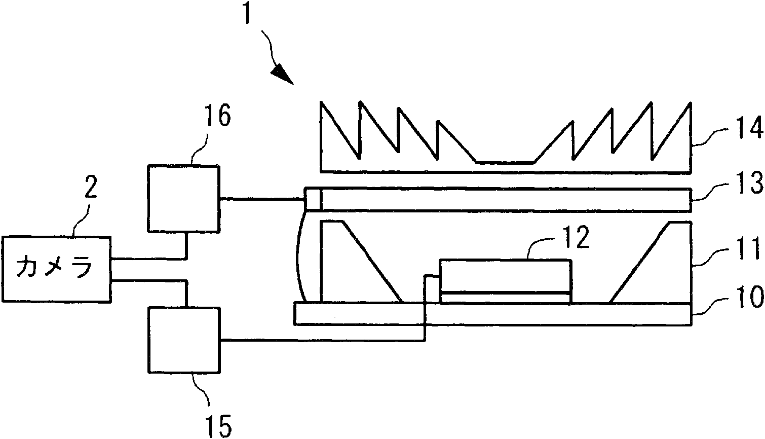
[0021] figure 1 is a schematic cross-sectional view showing the structure of a flash device according to one embodiment. figure 1 The shown flash device 1 is configured to include: an LED (light emitting element) 12 mounted on a substrate 10; a reflector 11 arranged to surround the LED 12; The electrochromic device (light control unit) 13; The lens 14 arranged on the upper part of the LED 12 sandwiching the electrochromic device 13; The driving circuit (first driving unit) 15 for driving the LED; And the driver for driving the electrochromic device Circuit (second drive unit) 16. The flash device 1 is connected to a camera 2 and used, for example, as shown in the figure. The flash device 1 of the present embodiment can be applied to either a direct drive method or a charging / discharging method. As shown in the figure, the substrate 10 is electrically connected to th...


PUM


Abstract

The invention provides a flashing device which has a simple structure, miniaturization realization an easy optical design. The flashing device (1) comprises a light-emitting component (12), a first drive unit (15) driving the light-emitting component, a light-gathering unit (14) disposed above the light-emitting component, a light control unit (13) disposed between the light-emitting component and the light-gathering unit, and a second drive unit (16) driving the light control unit. The light-gathering unit is formed by mixing at least a first Fresnel lens and a second Fresnel lens. The F value of the first Fresnel lens is different from that of the second Fresnel lens. When the light-emitting component is driven by the first drive unit and light is output from the light-emitting component, the second drive unit drives the light control unit, making the light transmission degree of the light control unit part, corresponding to the first Fresnel lens is relatively high, and the light transmission degree of the light control unit part, corresponding to the second Fresnel lens is relatively low.

Description

technical field [0001] The present invention relates to a flash device used in combination with an imaging device such as a digital camera. Background technique [0002] As a conventional example related to a flash device, a flash device including a light-condensing panel, a flash discharge tube, and a reflector is known (for example, refer to Patent Documents 1 and 2). In the flash device of this prior art, the outer surface of the condensing panel is a cylindrical surface, and the inner surface is a Fresnel lens surface. By changing the distance between the flash discharge tube and the reflector and the condensing panel, the flash Light distribution changes. [0003] Furthermore, as another conventional example of a flash device, a flash device including a Fresnel lens, an optical element for light shielding, a light emitting tube, and a reflector is known (for example, refer to Patent Document 3). The flash device of this conventional example divides the light-shielding...

Claims


Application Information

Patent Timeline
Patent Type & Authority Applications(China)
IPC IPC(8): G03B15/05F21V5/04
Inventor 高城英志河野圭真
Owner STANLEY ELECTRIC CO LTD
Features
  • R&D
  • Intellectual Property
  • Life Sciences
  • Materials
  • Tech Scout
  • Unparalleled Data Quality
  • Higher Quality Content
  • 60% Fewer Hallucinations
Learn More