Machine neck of vacuum brick extruding machine

A technology of vacuum brick extruder and machine neck, which is applied to ceramic forming machines and manufacturing tools, etc. It can solve problems such as poor lubrication and adjustment of rotary motion to linear motion, and achieve the effects of improving yield, increasing use efficiency, and saving energy.

Inactive Publication Date: 2011-08-17
赵培龙
View PDF4 Cites 1 Cited by
  • Summary
  • Abstract
  • Description
  • Claims
  • Application Information

AI Technical Summary

Problems solved by technology

[0008] In order to solve the problem of poor lubrication in the existing equipment and the inability to adjust the rotary motion of the mud to the straight line before it enters the machine head, the present invention provides a new vacuum brick machine neck: the machine neck is set in a vacuum Between the head of the brick extruder and the mud cylinder, the feature is that the machine neck is a two-stage structure, and a lubrication mechanism is installed in the upstream transition machine neck to lubricate the mud material in partitions

Method used


Image

  • Machine neck of vacuum brick extruding machine
  • Machine neck of vacuum brick extruding machine
  • Machine neck of vacuum brick extruding machine

Examples


Embodiment Construction

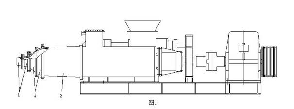
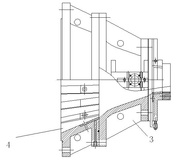
[0024] figure 1 Shown is a schematic diagram of the whole structure of the vacuum tile extruder. The vacuum tile extruder includes a mud cylinder 2. At the discharge end of the mud cylinder 2, a machine head 1 is installed, and the passage between the machine head 1 and the mud cylinder 2 is The compressor neck 3 is connected. Such as figure 2 As shown, the present invention adds a section of transition machine neck 4 between the upstream of compressor neck 3, that is, between mud cylinder 2, so that the overall structure of the machine neck is two-stage.

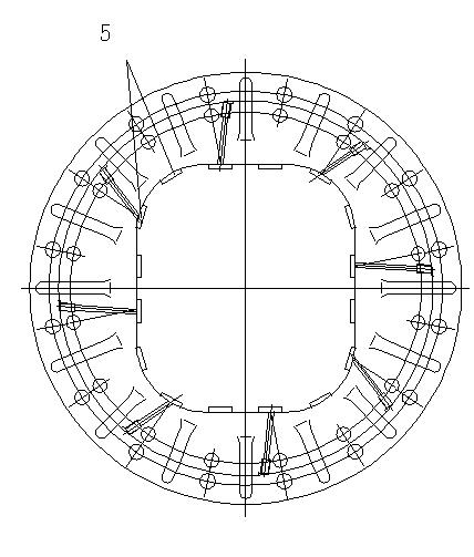
[0025] Such as image 3 , 4 As shown in , the transition machine neck 4 is the same as the compressor neck 3, and also has a conical structure, and its outer periphery and inner hole structure are transition sections between the mud cylinder 2 and the compressor neck 3. And on its inner wall, there are several guiding mechanisms, which can be image 3 , 4 As shown in , the ribs 5 penetrate through the transition neck...


PUM


Abstract

The invention discloses a machine neck of a vacuum brick extruding machine, and the machine neck provided by the invention is arranged between the machine head and mud cylinder of the vacuum brick extruding machine. The machine neck is in a two-section structure, and the interior of a transition machine neck arranged at the upstream of the machine neck is provided with a lubrication mechanism forcarrying out partitioned lubrication on mud materials. The transition machine neck is equipped with a plurality of guide mechanisms, so that under the interference of the guide mechanisms, the rotarymotion of the mud materials which enter into the transition machine neck from the mud cylinder is converted into a linear motion.

Description

technical field [0001] The invention relates to a neck of a vacuum brick extruder, in particular to a neck of a vacuum brick extruder with a lubricating structure and a guiding structure. Background technique [0002] In my earlier application number: 200710097510.5, titled: A high-efficiency energy-saving single-stage vacuum tile extruder, a vacuum tile extruder is recorded. The tile extruder includes mud Cylinder and machine head, the mud cylinder is provided with a material receiving box and a vacuum chamber, and a vacuum damping ring is provided near the input end of the vacuum chamber, and a spiral rib is provided on the lining of the mud cylinder, and a screw propulsion is also provided in the mud cylinder. Device, the output end of the mud cylinder is equipped with a machine head, and the extrusion mud cylinder is provided with a tapered section whose inner diameter is connected with the machine head and gradually decreases along the direction of mud material travel, ...

Claims


Application Information

Patent Timeline
IPC IPC(8): B28B3/20
Inventor 赵培龙
Owner 赵培龙
Why Eureka
Try Eureka