Injection molding method and injection molding device

A technology for injection molding and mounting bodies, which is applied in the field of injection molding devices, can solve the problems of reduced mold durability, increased cost, and increased manufacturing difficulty, and achieves improved durability, cost suppression, and low manufacturing difficulty Effect

Inactive Publication Date: 2011-08-17
FUJISEIKO
View PDF6 Cites 3 Cited by
  • Summary
  • Abstract
  • Description
  • Claims
  • Application Information

AI Technical Summary

Problems solved by technology

[0008] Of course, in order to solve the above problems, a mold structure that does not generate burrs is required. In this case, the difficulty of making the mold increases, the cost increases, and the durability of the mold decreases.
In addition, the following problems will occur: since the pressing is performed at a temperature below the softening point of the synthetic resin, there is a difference in the temperature of the synthetic resin between the injection part of the synthetic resin and a part far away from the injection part, and when pressing, the temperature of the synthetic resin is reduced. Differences in compression density lead to differences in appearance quality of synthetic resin molded products

Method used


Image

  • Injection molding method and injection molding device
  • Injection molding method and injection molding device
  • Injection molding method and injection molding device

Examples


Embodiment Construction

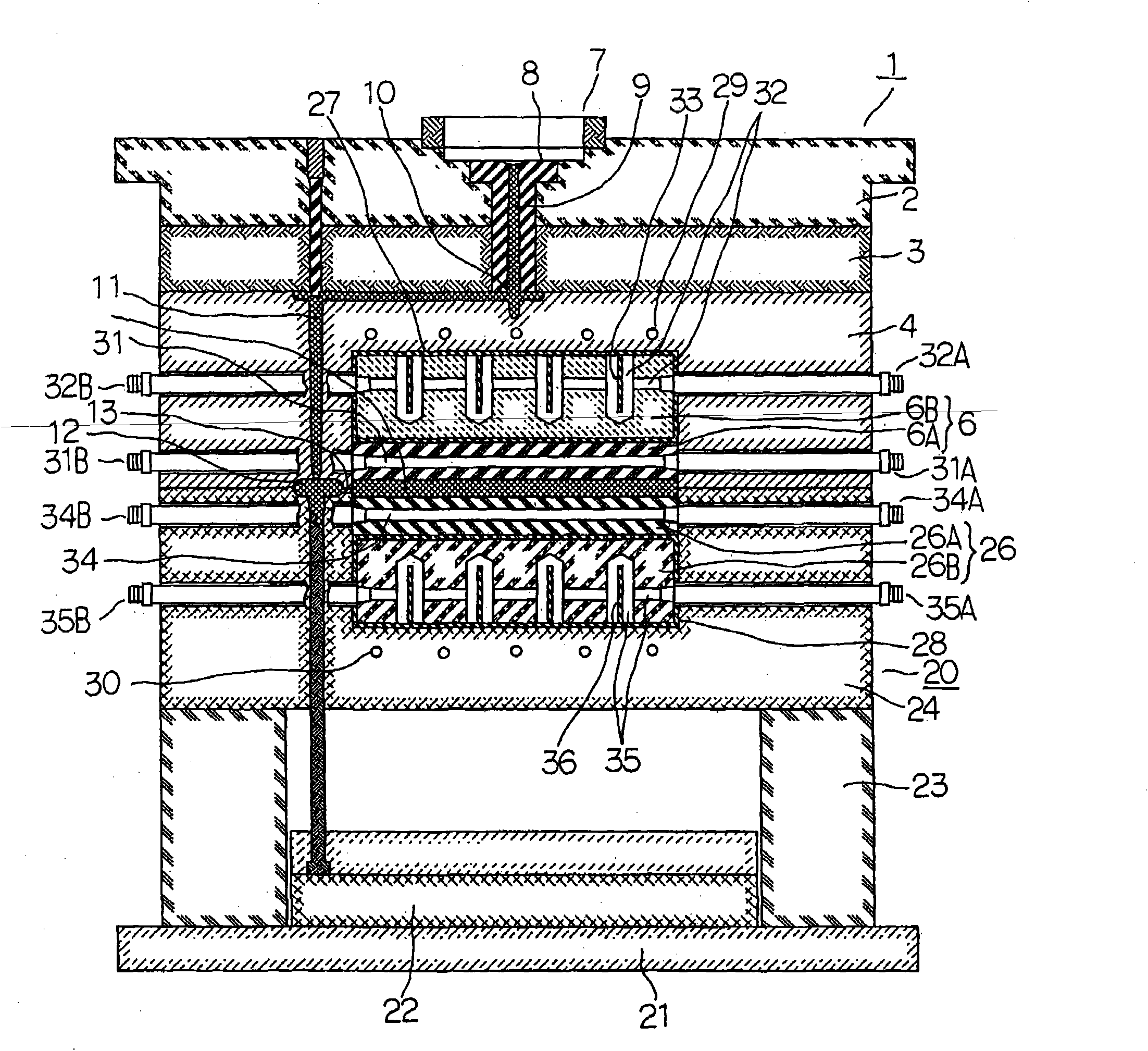
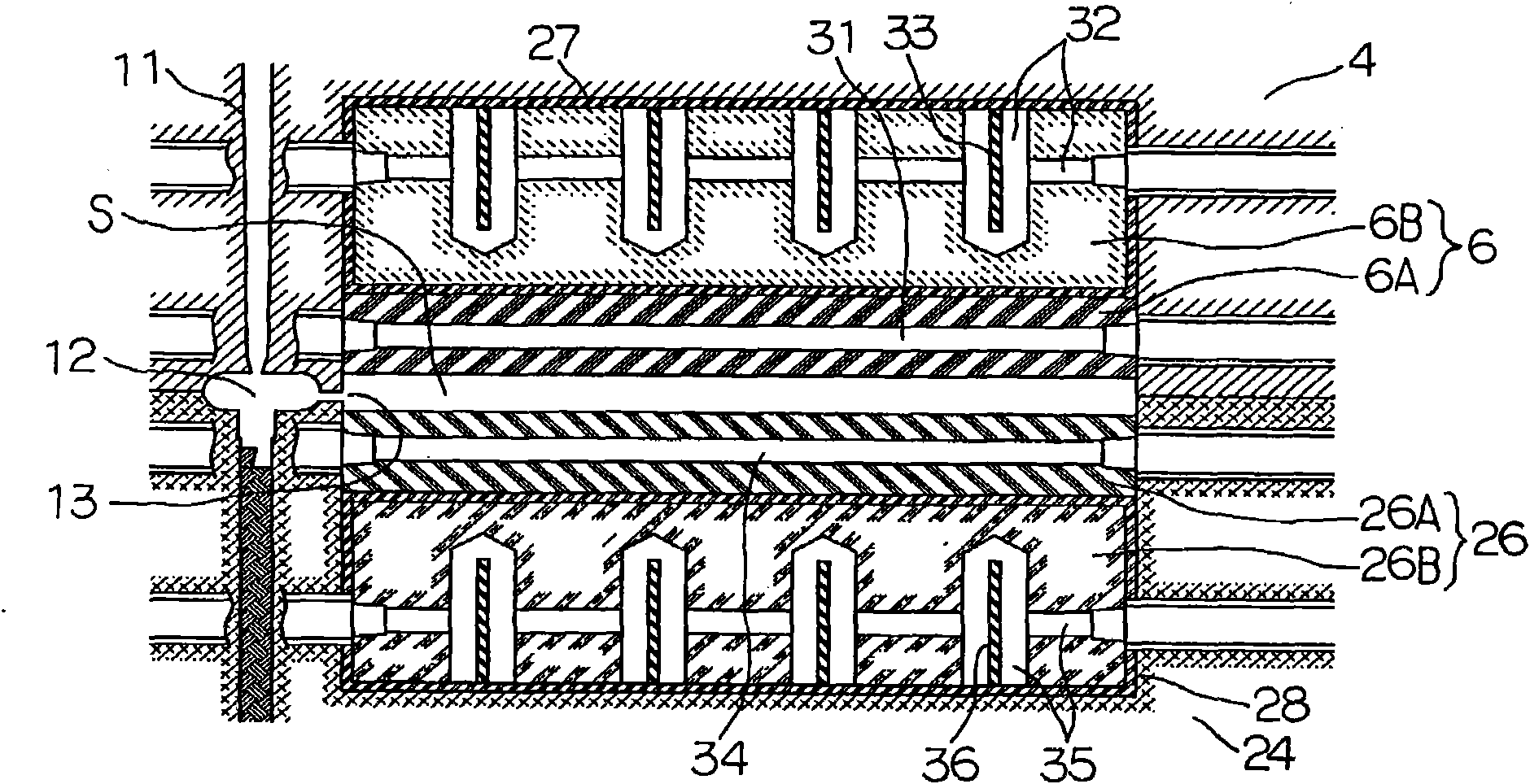
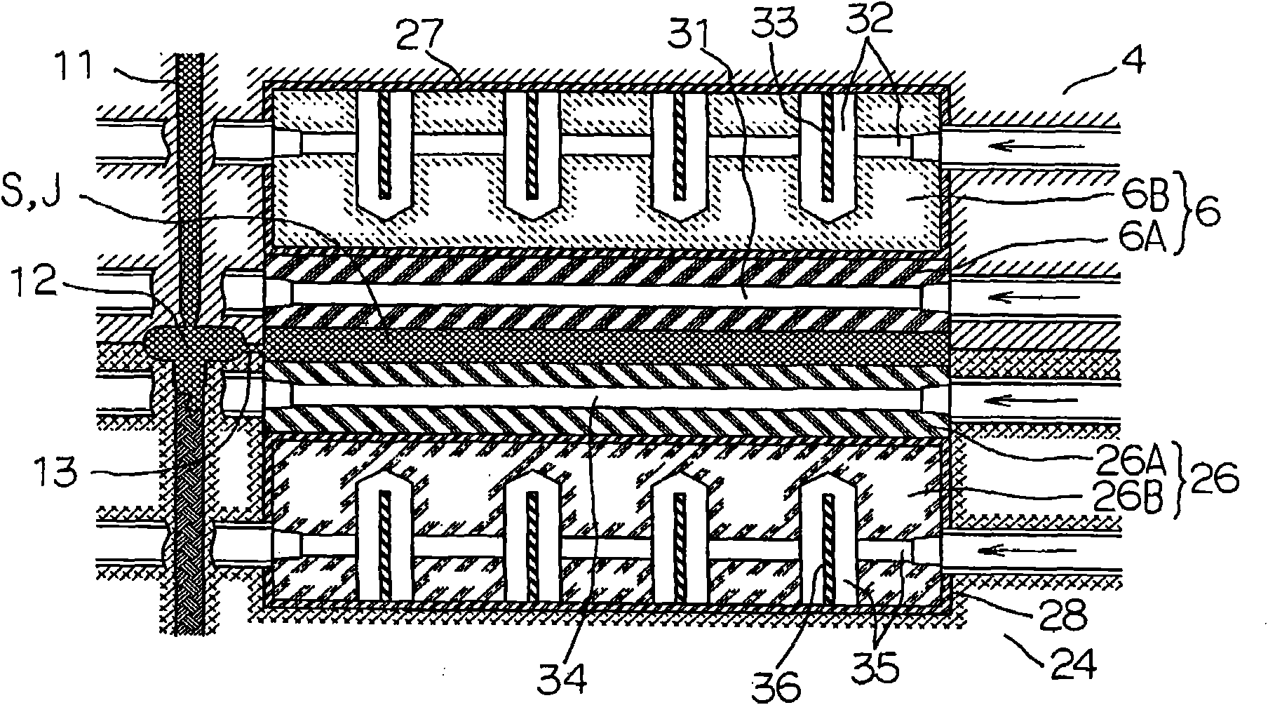
[0054] Below, based on Figure 1 to Figure 5 Embodiments of the present invention will be described. First, based on figure 1 The overall configuration of the injection mold according to the first embodiment of the present invention will be described. 1 is a fixed-side assembly mounted on a fixed platen (not shown) by bolts, and the fixed-side assembly 1 includes: a first fixed-side base plate (base plate) 2 , The fixed-side second base plate 3 fixed to the fixed-side first base plate 2, the fixed-side third base plate 4 fixed to the fixed-side second base plate 3 by screws, and the concave portion arranged on the fixed-side third base plate 4 The fixed mold part 6 inside and fixed to the third bottom plate 4 on the fixed side by screws is arranged on the first bottom plate 2 on the fixed side at a position that is biased to the fixed plate and locates the first bottom plate 2 on the fixed side. A locating ring 7 of the fixed disk, a sprue bush 8 arranged adjacent to the lo...


PUM


Abstract

Disclosed is an injection molding method and an injection molding device, capable of compressing synthetic resin in a die cavity without generating burrs, thereby producing synthetic resin products with excellent appearance. The producing of the die is easy, low in cost and higher in durability. The method includes feeding heating media to a heating medium path of a sleeve sheet of a fixed die portion and a mobile die portion for heating to a temperature higher than the softening point of the synthetic resin; injecting and filling the molten synthetic resin into a die cavity and pressurizing; feeding heating media to a heating medium path of a sleeve sheet installation body of a fixed die portion and a mobile die portion for heating so as to make the sleeve sheet installation body undergo thermal expansion before or after pressurizing, supplying coolant to the heating medium path of the sleeve sheet to cool after the thermal expansion and compressing the synthetic resin with a pressure higher than injection pressure of the synthetic resin and at the same time curing the synthetic resin.

Description

technical field [0001] The present invention relates to an injection molding method and an injection molding device. In a state where a fixed mold and a movable mold are closed, molten synthetic resin is injected and filled into a cavity, and the synthetic resin is injected in the mold. to compress. Background technique [0002] As for the injection molding method of synthetic resin, for example, as disclosed in Patent Document 1 and the like, there has been proposed a technique in which, before injecting molten synthetic resin, a surface side cavity for molding the surface side of a molded product is formed. The forming surface is heated to improve transferability. [0003] prior art literature [0004] patent documents [0005] Patent Document 1 Japanese Patent Laid-Open No. 6-254924 [0006] However, in the injection molding method with the pressing function of compressing the synthetic resin in the injection molding mold, to the extent that the filled synthetic resin...

Claims


Application Information

Patent Timeline
Patent Type & Authority Applications(China)
IPC IPC(8): B29C45/26B29C45/73
CPCB29C45/14B29C45/561B29C45/72B29C2045/14868
Inventor 横山胜助金子光雄
Owner FUJISEIKO
Why Eureka
Try Eureka