
Arch-after-girder construction method of large-span steel box tacked arch bridge

A beam first, arch later, and construction method technology, which is applied to bridges, bridge parts, bridge construction, etc., can solve the problems of extended construction period of box girder erection, complicated construction procedures, and unfavorable construction organization, etc., to shorten the erection period and simplify the construction process Convenience and good economic benefits

Active Publication Date: 2013-01-30
CCCC TUNNEL ENG
View PDF7 Cites 0 Cited by
  • Summary
  • Abstract
  • Description
  • Claims
  • Application Information

AI Technical Summary

Problems solved by technology

The traditional construction method has the following deficiencies and defects: 1) The construction process is complicated and the construction period is long; 2) If the steel box stacked arch bridge is located on the girder erection channel, after the arch ribs, suspenders and other important load-bearing structures are completed, the girder transporter must pass Erection of box girders, the result is that the construction period of box girders is prolonged and the cost of beam yards is increased; 3) Traditional hoisting methods such as arch rib segmental support method and cable crane are greatly restricted by terrain factors, which are not conducive to construction organization, and the construction cost is relatively high

Method used


Image

  • Arch-after-girder construction method of large-span steel box tacked arch bridge
  • Arch-after-girder construction method of large-span steel box tacked arch bridge
  • Arch-after-girder construction method of large-span steel box tacked arch bridge

Examples


Embodiment Construction

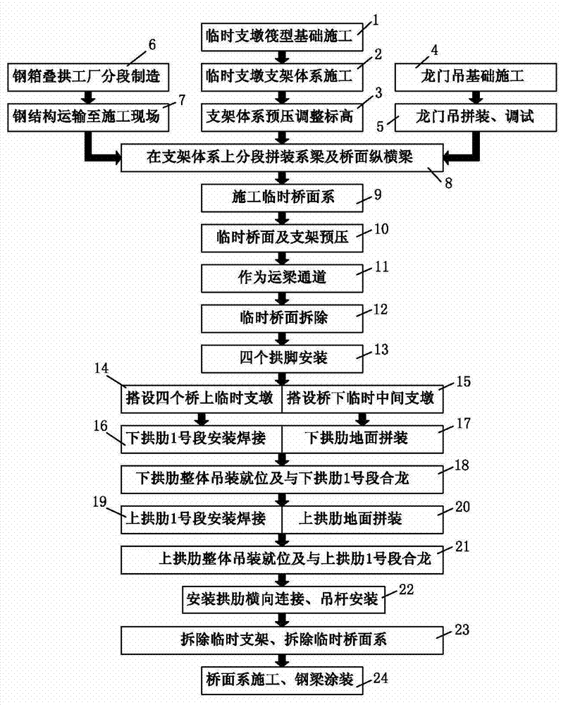
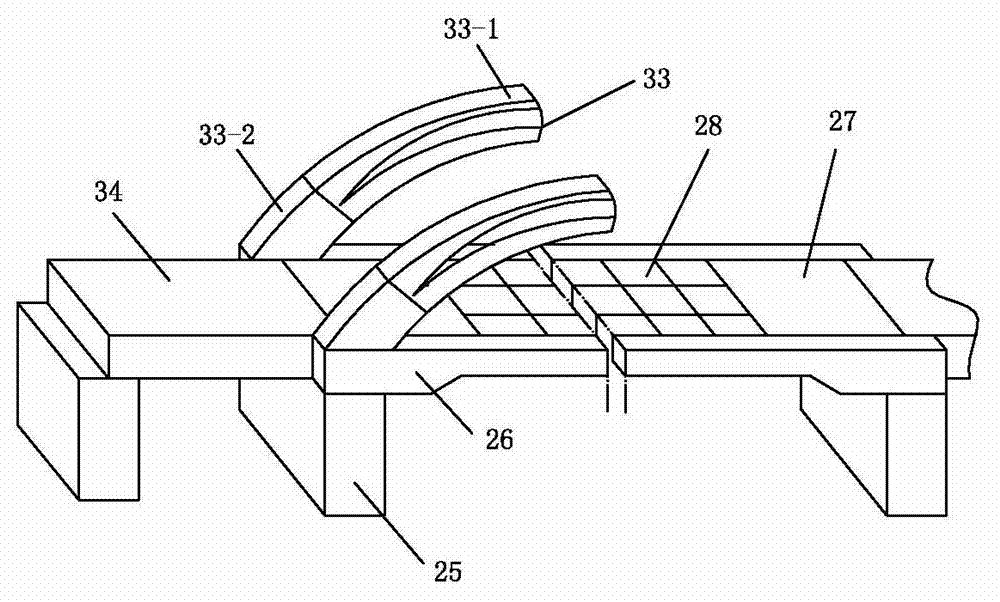
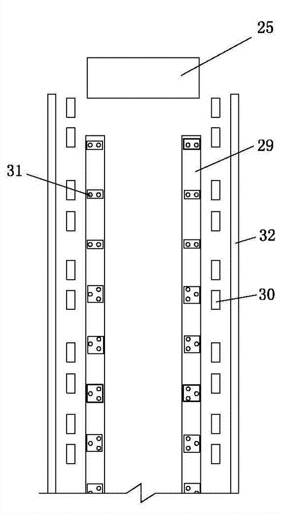
[0028] For an example of the construction method of the long-span steel box stacked arch bridge "beam first and then arch", see figure 2 , image 3 , Figure 4 and Figure 5 , the method includes the tie beam 26 spanning the piers 25 at both ends, the structural construction of the end beam 27 and the vertical and horizontal beam 28, the construction of the arch span structure and the construction of the bridge deck, and the sequence of steps includes:

[0029] a. At first build two temporary reinforced concrete strip foundations 29 respectively at the ground projections of the steel beam bottoms on both sides of the steel structure bridge to be built, and set up steel beam assembly platforms 30 on the outside of the two strip foundations, the platforms The height is less than 1.2 meters. A plurality of temporary buttresses 31 are arranged on the reinforced concrete strip foundation. The gantry crane track foundation is correspondingly built on the outside of the two-row st...


PUM


Abstract

The invention relates to an arch-after-girder construction method of a large-span steel box tacked arch bridge. The construction method comprises the following steps of: respectively building two temporary reinforced concrete bar-shaped bases on the ground at the bottom parts of steel girders on two sides of a to-be-built steel-structure bridge; mounting a plurality of temporary supporting piers on the reinforced concrete bar-shaped bases; respectively mounting steel girder assembling platforms on two external sides of the two bar-shaped bases; and paving portal crane rails on two sides of the steel girder assembling platforms and mounting two portal cranes. In the construction method, arch ribs, lifting rods and bridge surfaces engineering are carried out after system girders, end transverse girders and vertical transverse girders are mounted to form a whole stressed system by combining with temporary main supporting piers. The construction method has the advantages of low construction investment, specific structure stress, and simple and convenient construction process, and can realize parallel construction; all the steel components are hoisted by adopting the running-type portal canes, thereby reducing a great amount of mounting and dismantling work of the scaffoldings in the high altitude, and reducing the mounting period of the box girders; and the steel components can be assembled under the bridge during the transporting time of thebox girders, which increases the safety coefficients, and improves the structural quality.

Description

technical field [0001] The invention belongs to the field of bridge construction, and in particular relates to a construction method for a long-span steel box-stacked arch bridge of "beam first and arch later". In this method, after the tie beams, end beams, and longitudinal beams are installed and combined with the temporary pier structure to form an overall stress system, the arch ribs, suspenders, and bridge deck systems are carried out, which greatly shortens the erection period of the box girder and is effective. The delay of the construction period caused by the construction of the steel bridge arch is avoided. Background technique [0002] On urban roads and highways, the traditional construction method of steel box stacked arch bridges mainly adopts "arch first, then girder". The arch ribs are symmetrically assembled, and the arch rib segments are hoisted and assembled by crawler cranes, and finally the second phase of the bridge deck is constructed with dead load. ...

Claims


Application Information

Patent Timeline
Patent Type & Authority Patents(China)
IPC IPC(8): E01D21/00E02D27/01E01D19/02
Inventor 谢建国林鹏凯傅鑫彬郝良秋魏斌周锋刘东宁岳小东李路生吴全立刘洋
Owner CCCC TUNNEL ENG
Learn More