
Optical isolator and isolation method

An implementation method and reverse isolation technology, which can be used in instruments, optics, nonlinear optics, etc., can solve the problems of difficulty in making optical isolators, and achieve the effect of increasing the spectral range and simplifying the system structure.

Inactive Publication Date: 2013-01-09
XI'AN INST OF OPTICS & FINE MECHANICS - CHINESE ACAD OF SCI
View PDF0 Cites 0 Cited by
  • Summary
  • Abstract
  • Description
  • Claims
  • Application Information

AI Technical Summary

Problems solved by technology

Similarly, the error and precision control during the manufacture and installation of the two polarizers and analyzers arranged at 45° to each other are relatively strict, which brings difficulties to the manufacture of optical isolators.

Method used


Image

  • Optical isolator and isolation method
  • Optical isolator and isolation method
  • Optical isolator and isolation method

Examples


specific Embodiment

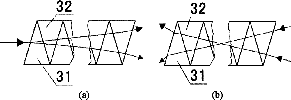
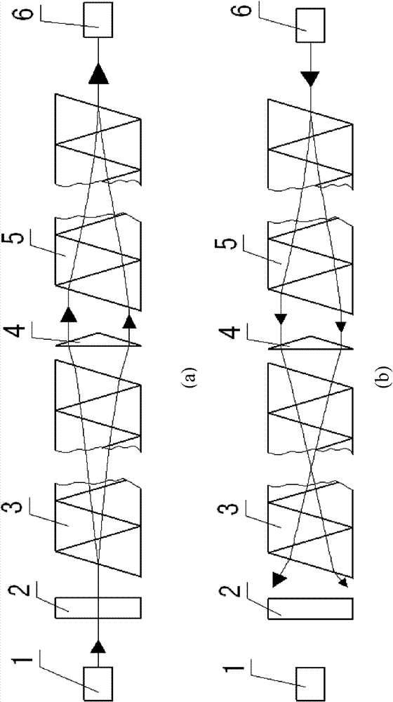
[0032] An optical isolator that allows light to pass unimpeded during forward transmission, but cannot return along the original optical path during reverse transmission, and cannot enter the input end. The isolator uses the non-reciprocal circular birefringence characteristics of magneto-optical glass and a wedge-shaped refractive crystal. The refraction collimation function and the reciprocal circle birefringence characteristic of the natural optical rotation crystal to realize the function of the optical isolator. The task of the present invention is achieved through the following schemes: incident fiber 1, polarizer 2, magneto-optical wedge glass group 3, tapered refractive prism 4, natural-rotation wedge crystal group 5, exit fiber 6, magnetic ring (magnet tube) 9) The optical path device composed of 9 is fixed in the inner packaging tube 10, and they are all on the same optical axis. The inner packaging tube 10 is covered with a sealed metal shell and the outer packaging s...


PUM


Abstract

The invention provides an optical isolator and an isolation method. The forward propagation and reverse isolation of an optical wave are realized, and the technical problems of the optical isolator which is manufactured based on a Faraday rotation principle in the prior art are solved. In the invention, by a linearly polarized light which is generated by a polarizer in an optical path system, thenon-reciprocal circular double-refraction property of magnetic rotation glass and the reciprocal circular double-refraction function of a natural rotation crystal, forward lights can be re-focused atan output end, and reflected lights cannot be focused at a forward input end and further isolated after passing through the magnetic rotation wedge-shaped glass, so that the aim of light one-way transmission is fulfilled. The invention has the advantages of high isolation of a reverse light, low insertion loss, large operation bandwidth and the like.

Description

Technical field [0001] The invention belongs to an optical passive device and an application, and in particular relates to an optical isolator that realizes forward propagation and reverse isolation of light waves and an implementation method thereof. Background technique [0002] In the optical fiber communication system, the laser transmitter is sensitive to the reflected light reflected by the Rayleigh spot between the fiber joints and various devices in the system and the optical fiber itself. After the reflected light enters the laser cavity, the laser transmitter emits light. The optical signal is noisy, which affects the operation of the entire system, and also causes the deterioration of the system transmission performance. The gain of the optical amplifier changes and self-excitation is generated, which will eventually lead to the generation of bit errors, causing the entire optical fiber communication system to fail to work normally. The problem can be solved by connect...

Claims


Application Information

Patent Timeline
Patent Type & Authority Patents(China)
IPC IPC(8): G02F1/09
Inventor 吴易明李春艳高立民
Owner XI'AN INST OF OPTICS & FINE MECHANICS - CHINESE ACAD OF SCI
Learn More