
Method for controlling machining track of numerically-controlled machine tool

A control method and technology of CNC machine tools, applied in the field of CNC machine tool machining track control and CNC machine tool adjustment processing effect control field, can solve the problems of increased data processing capacity of CNC machine tool system, increased system software and hardware requirements, and increased processing file length, etc. To achieve the effect of avoiding data processing volume, wide application range and avoiding increase

Active Publication Date: 2011-08-17
SHANGHAI WEIHONG ELECTRONICS TECH
View PDF5 Cites 4 Cited by
  • Summary
  • Abstract
  • Description
  • Claims
  • Application Information

AI Technical Summary

Problems solved by technology

This method leads to a sharp increase in the data of the generated processing files. If it is necessary to increase the processing file with a general accuracy of 0.2 wires to an accuracy of 0.1 wires, the length of the processing file will be doubled.
And the length of the processing file increases, the data processing capacity of the CNC machine tool system also increases, the requirements for the system software and hardware increase, and the cost of the CNC machine tool increases accordingly

Method used


Image

  • Method for controlling machining track of numerically-controlled machine tool
  • Method for controlling machining track of numerically-controlled machine tool
  • Method for controlling machining track of numerically-controlled machine tool

Examples


Embodiment Construction

[0021] In order to understand the technical content of the present invention more clearly, the following examples are given in detail.

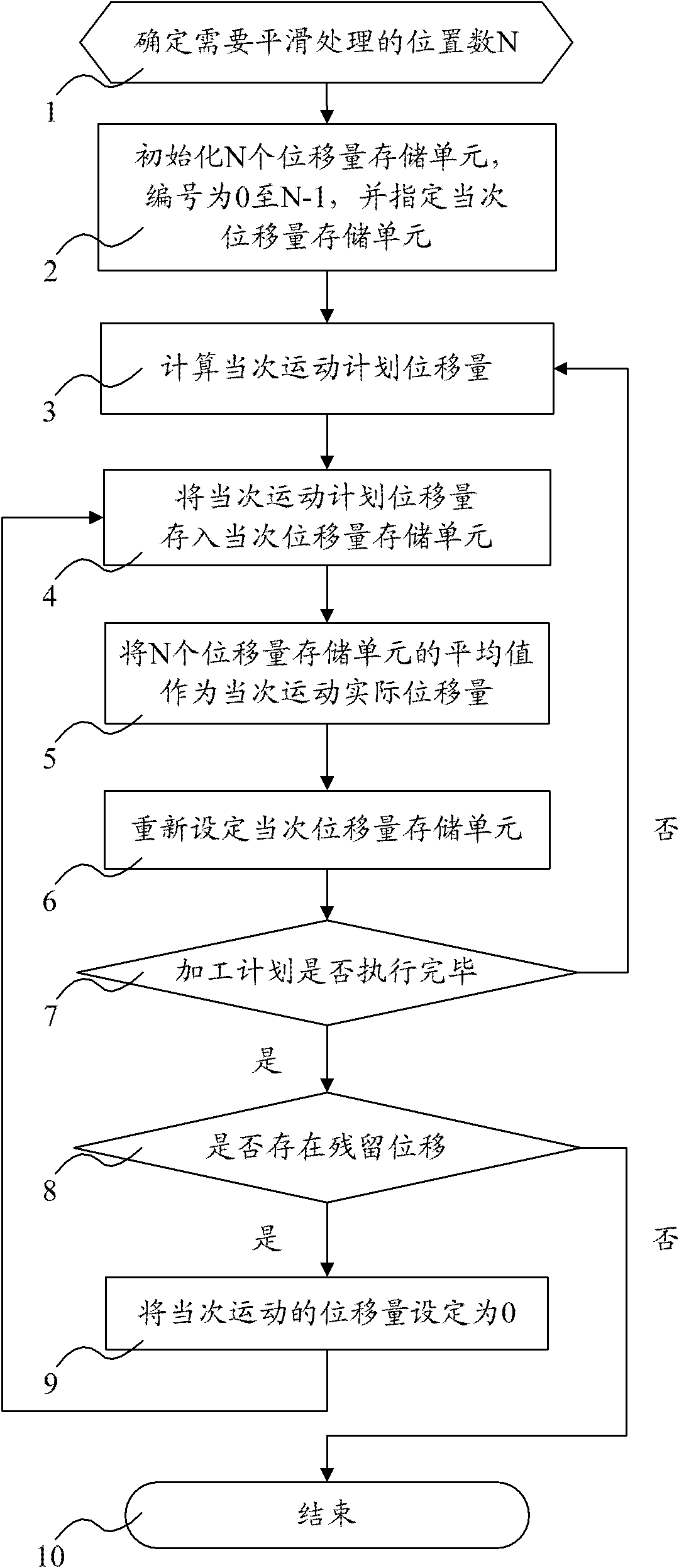
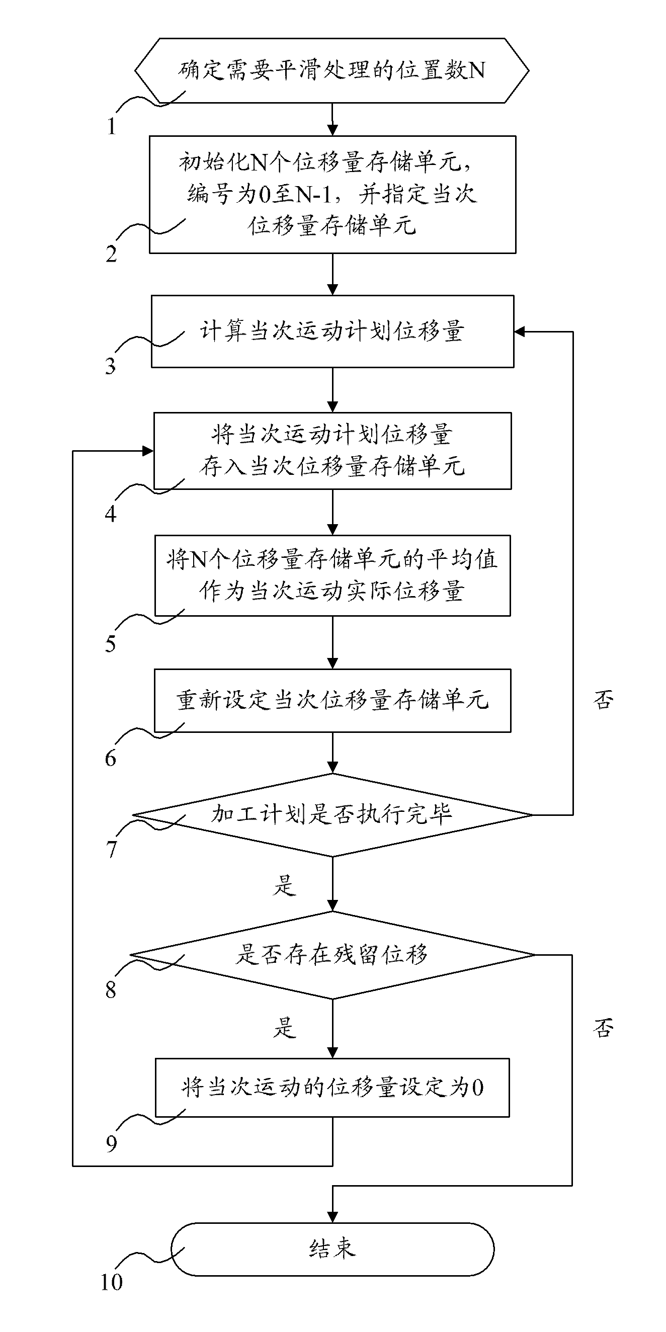
[0022] see figure 1 As shown, it is a flow chart of the steps of the CNC machine tool machining trajectory control method of the present invention.

[0023] In one embodiment of the present invention, this CNC machine tool processing track control method comprises the following steps:

[0024] (1) Determine the number N of positions that need to be smoothed according to the processing plan;

[0025] (2) Initialize N displacement storage units, number each displacement storage unit from 0 to N-1, and specify the numbering of the current displacement storage unit;

[0026] (3) Calculate the displacement of the current motion plan according to the processing plan;

[0027] (4) storing the displacement amount of the current motion plan into the displacement amount storage unit;

[0028] (5) The average value of N displacement storage units is...


PUM


Abstract

The invention relates to a method for controlling a machining track of a numerically-controlled machine tool. The method comprises the following steps of: determining the number N of positions to be smoothly machined; initialing N displacement storage units and storing the planned displacement of current movement in a machining plan into a current displacement storage unit; taking an average value of the N displacement storage units as the actual displacement of the current movement; and circulating the process to finish the machining. By utilizing the method disclosed by the invention, the displacement in single time of movement in the machining plan is realized by being dispersed into N times of movements so that the displacement variables among multiple times of close movements are reduced, the fitting degree of a machined free-form surface is better, and the degree of finish of the machined surface is higher; therefore, with the method disclosed by the invention, under the condition that a machining file does not need to be lengthened, the degree of finish of the machined free-form surface is increased, the increase of data processing amount of the numerically-controlled machine tool is avoided, and the cost of the numerically-controlled machine tool is reduced under the condition that application requirements are same.

Description

technical field [0001] The invention relates to the field of control of numerical control machine tools, in particular to the field of control methods for adjusting machining effects of numerical control machine tools, in particular to a method for controlling machining tracks of numerical control machine tools. Background technique [0002] Modern technology has gradually increased the requirements for the processing effect of CNC machine tools, especially for the smoothness of free-form surfaces. In the CNC machine tool control system, there are only two workpiece processing methods: straight line and arc. Free-form surfaces need to be processed. Generally, processing files are generated by special CAM software, and they are fitted by continuous short straight line segments. The finish depends on the accuracy when generating processing files. Aiming at the actual requirement of high finish, the common solution is to improve the precision of the generated processing files. ...

Claims


Application Information

Patent Timeline
IPC IPC(8): G05B19/19
Inventor 方敏吴典焦逸
Owner SHANGHAI WEIHONG ELECTRONICS TECH
Learn More