Logic-compatibility-based digital circuit fault diagnosis method and system
What is Al technical title?
Al technical title is built by PatSnap Al team. It summarizes the technical point description of the patent document.
A digital circuit, compatibility technology, applied in the field of digital circuit fault diagnosis and system based on logic compatibility
Inactive Publication Date: 2011-08-17
DALIAN MARITIME UNIVERSITY
View PDF1 Cites 9 Cited by
Summary
Abstract
Description
Claims
Application Information
AI Technical Summary
This helps you quickly interpret patents by identifying the three key elements:
Problems solved by technology
Method used
Benefits of technology
Problems solved by technology
[0008] In China, there are few systematic studies on modeling, conflict identification, and candidate generation. The present invention is based on the research results of the predecessor
Method used
Image
Click on the blue label to locate the original text in one second.
Reading with bidirectional positioning of images and text.
Examples
no. 1 approach
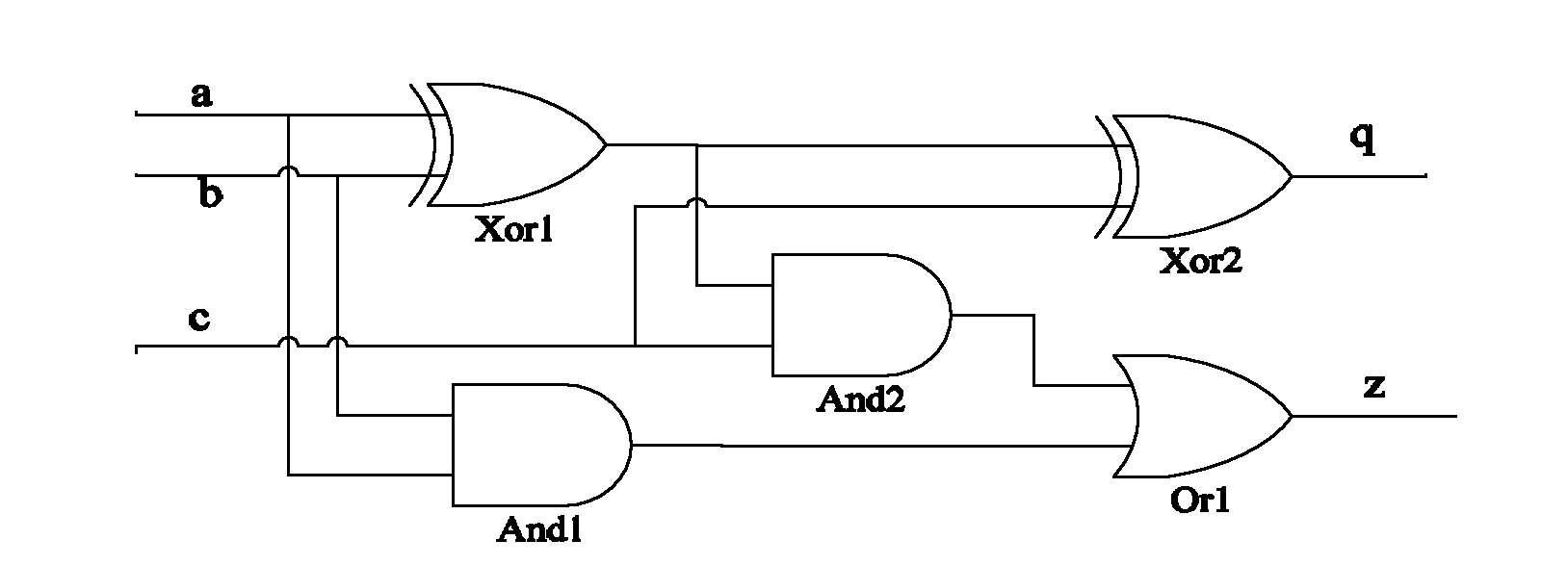
[0057] Below to image 3 Take the full adder shown as an example to explain the above basic steps.
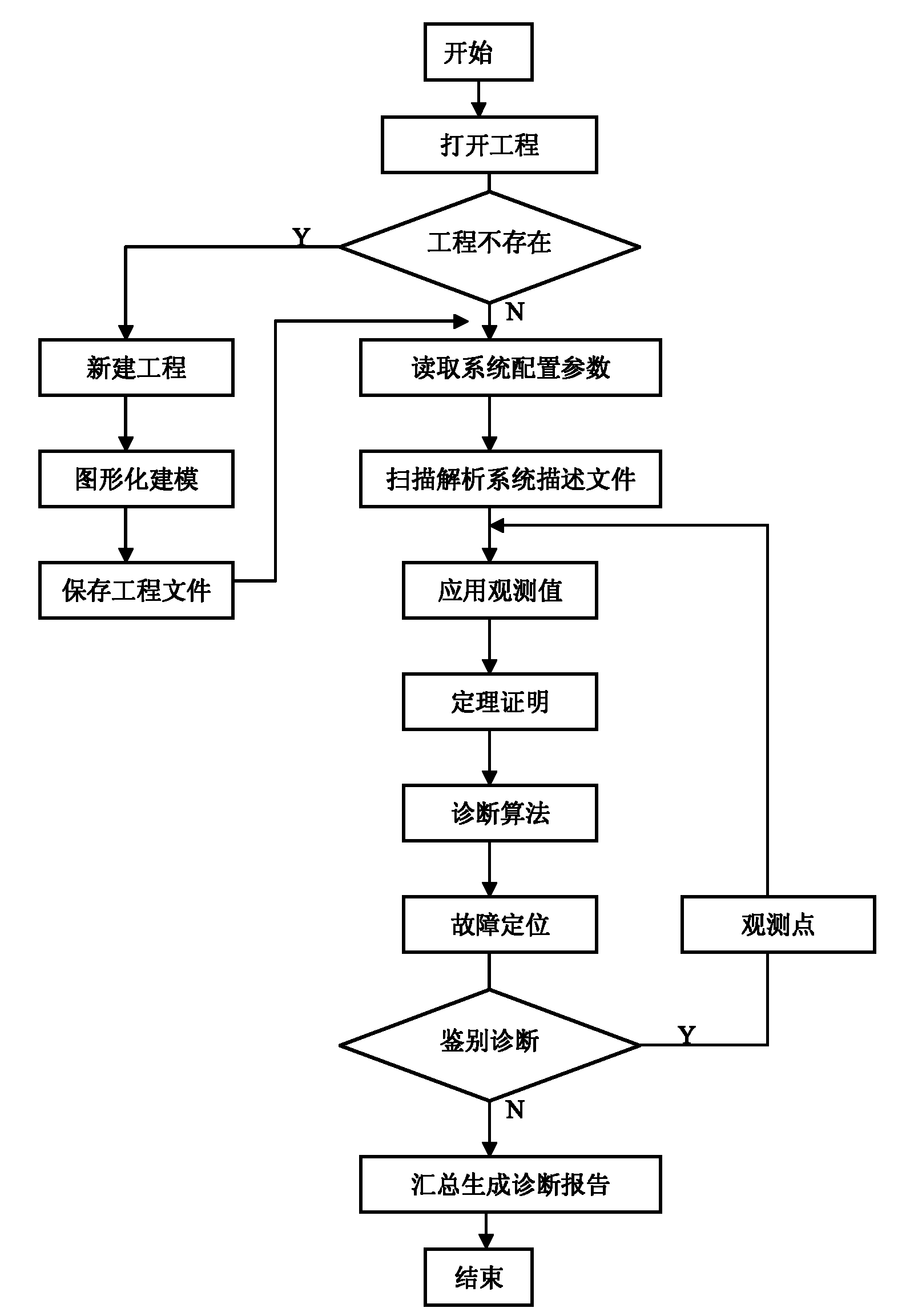
[0058] 1) After the program starts, the user uses the dialog box to specify the location to open a project.
[0059] 2) The user builds a full adder digital circuit as shown in the above figure through the digital circuit graphical modeling unit 101 . Here, the user selects gate-level standard components AND gates And1 and And2, OR gate Or1, XOR gates Xor1 and Xor2. The user drags and drops them to the position in mind, and then connects the input and output ports of the component - taking Xor1 as an example, its two input ports are connected to a and b respectively, and its output port is connected to Xor2 and And2. In this way, a complete full adder circuit is built.
[0060] 3) The user uses the description configuration unit 102 to set the values of the circuit input terminals a, b, c and the actual observed values of the output terminals q, z, then set the upper lim...
no. 2 approach
[0075] Such as Figure 4 The circuit shown is used to illustrate the implementation and application of this test method. In this circuit, the components include an adder DCAdd, a multiplier DCMul, an AND gate DCAnd, an OR gate DCOr, and a NOT gate DCOr. We have compiled a serial number for all components in the circuit, such as the component numbered 1 is an adder DCAdd. For the convenience of the following description, we will use the serial number of the component to refer to the component.
[0076] The system can randomly select a component and make it work in a faulty manner, such as an incorrect output value at an output. In the experiment, we choose component 13 (a multiplier DCMul) and make it work in a certain faulty way, for example, let its output value be out(13)=8*in2(13), that is, output the input of its input port 2 8 times the value. Using the method provided by the present invention, the diagnostic steps are as follows:
[0077] 1) After the program is sta...
PUM
Abstract
The invention discloses a logic-compatibility-based digital circuit fault diagnosis method and a logic-compatibility-based digital circuit fault diagnosis system. The method comprises the following steps of: building a diagnosed digital circuit system by a user through a digital circuit graphical modeling unit, then setting the parameters of the circuit by using a description configuration unit, expressing a digital circuit graph by using an AD2L language and storing the digital circuit graph in a file form; reading the digital circuit description file stored by the description configuration unit by the user through an AD2L language resolving unit, performing front and rear propagation through a theorem proving unit by using the parameters provided by the user, and recording the conflict; performing diagnosis and solving by using a diagnosis algorithm unit; and highlighting a suspicious component on the graphical digital circuit by using a fault positioning unit, and generating a diagnosis test report. The system has the functions of conflict identification and candidate generation and detection, the whole operating process is simple and spends short time, and judgment and positioning of the system on fault points do not depend on experience of operators or experts.
Description
technical field [0001] The invention relates to a digital circuit fault diagnosis method and system based on logic compatibility. Background technique [0002] In recent years, the research and application of model-based diagnosis has been a hot spot in the field of diagnostic testing. It has developed rapidly and various solutions have emerged. Compared with traditional diagnostic methods, model-based diagnosis developed in recent years has obvious advantages, that is, it does not depend on experience, is independent of equipment, and the model can be reused. [0003] Traditional diagnosis is based on experience (also known as diagnosis based on "shallow knowledge"). This diagnosis mainly relies on the empirical knowledge of domain experts on the diagnostic object. This method has a strong dependence on the application field, that is, for a A diagnostic to which an object applies cannot be used on another diagnostic object. There are two main types of computer diagnostic ...
Claims
Application Information
Patent Timeline
Application Date:The date an application was filed.
Publication Date:The date a patent or application was officially published.
First Publication Date:The earliest publication date of a patent with the same application number.
Issue Date:Publication date of the patent grant document.
PCT Entry Date:The Entry date of PCT National Phase.
Estimated Expiry Date:The statutory expiry date of a patent right according to the Patent Law, and it is the longest term of protection that the patent right can achieve without the termination of the patent right due to other reasons(Term extension factor has been taken into account ).
Invalid Date:Actual expiry date is based on effective date or publication date of legal transaction data of invalid patent.