Apparatus and Method for Energy Recovery

Inactive Publication Date: 2010-02-11
XSORB ECO TECH
View PDF10 Cites 4 Cited by
  • Summary
  • Abstract
  • Description
  • Claims
  • Application Information

AI Technical Summary

Benefits of technology

[0056]This process can be accomplished in less than 6 months, even in as little as one month, but then higher temperatures and higher heat flows are needed. This possibly results in a higher degradation of the desiccant resulting in a shorter life cycle of the desiccant.
[0057]The regeneration of the desiccant can use solar energy and ambient heat (a

Problems solved by technology

Emission of this humid flue gas heat to the atmosphere afflicts an appreciable loss of a potential humid heat energy which could be recovered.
However, low temperatures and high flow rates of cold fluids are needed to condense an appreciable amount of water from flue gases.
Lest it be for preheating an enormous flow rate of cold air, these low heat exchange temperatures are generally not suitable for transfer of heat

Method used


Image

  • Apparatus and Method for Energy Recovery
  • Apparatus and Method for Energy Recovery
  • Apparatus and Method for Energy Recovery

Examples


Embodiment Construction

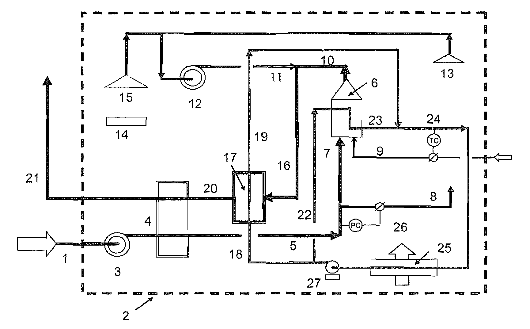
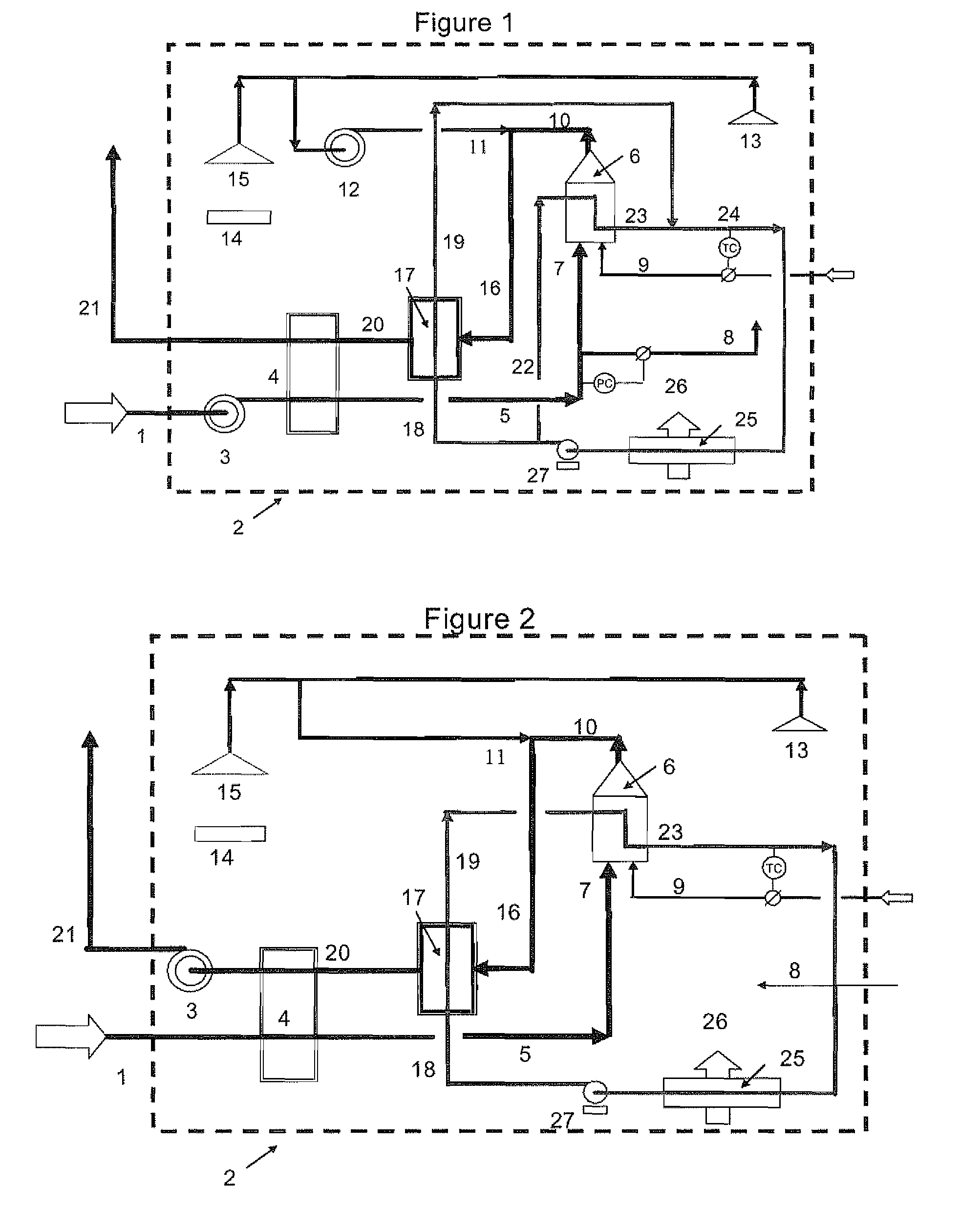
[0071]In a preferred embodiment as depicted in FIG. 1, humid cold air (1) enters the residential dwelling walls (2) through an appropriate duct and is passed to the suction of a forced draft motor driven fan (3). Alternatively, as shown in FIG. 2, the forced draft fan (3) can be replaced by an identically sized induced draft fan just before the flue stack (21) in the chimney.

[0072]In the forced draft version as depicted in FIG. 1, the discharge of the fan is passed via appropriate ducting through a gas to gas compact plate and fin heat exchanger (PFHE) (4), preferably constructed of aluminium, inside the dwelling, wherein it is preheated by warmer expelled dry air and flue gasses (20) before being taken via appropriate ducting as stream (5) within the dwelling to various points. Some of the warmed air at a slightly positive pressure is passed through appropriate ducting to the fuel fired water heater (6) as combustion air (7). A part of the warm air is passed through a back pressure...


PUM


Abstract

There is provided a heating system for a building comprising; i) a heater; ii) a media flow passage through which a medium heated by the heater passes in order to distribute heat through the building; and iii) a heat recovery apparatus for recovering latent heat of adsorption from a humid gas. The heat recovery apparatus comprises a) a gas flow passage connected at one end to a source of humid gas; b) a desiccant material provided within the gas flow passage such that the humid gas contacts the desiccant material and water vapour is adsorbed releasing latent heat of adsorption; wherein the media flow passage and gas flow passage are in heat exchanging relationship, such that when the desiccant material adsorbs water vapour from the exhaust gas the latent of the adsorption is at least partially transmitted to the medium.

Description

FIELD OF THE INVENTION[0001]The present invention relates to a building comprising an apparatus for recovering latent heat of adsorption from a humid gas source associated with the building, in particular a residential or commercial dwelling. The invention furthermore relates to a method of recovering latent heat of adsorption from a humid gas, in particular an exhaust gas associated with a residential or commercial dwelling.BACKGROUND[0002]Internal heating for comfort of residential and commercial dwellings is very often practised by heating and circulating water in carbonaceous-fuel-fired or electric heaters and passing the hot water through convection heat exchangers (often called radiators) to heat the inside surrounding air while cooling the water. The cooled water is then returned to the fired heater to be reheated. Usually the water is heated to as high as 80° C. and the return water is cooled to near ambient room temperature as low as 20° C. so as much as 60 kcal / kg of sensi...

Claims


Application Information

Patent Timeline
IPC IPC(8): B01D53/02F24D3/00H05B1/00
CPCF24D12/02F24D2200/18Y02B30/14Y02B30/102F24H8/00Y02B30/00Y02E60/14F28D20/02
Inventor MINKKINEN, ARI ANTERO
Owner XSORB ECO TECH
Why Eureka
Try Eureka