Winding core and wafer-processing belt wound on same

A technology of wafer processing and winding cores, which is applied in the fields of electrical components, novolak epoxy resin adhesives, semiconductor/solid-state device manufacturing, etc., can solve the problems of limited support layer width, narrow support layer width, influence, etc., to achieve Effect of reducing winding pressure and suppressing transfer marks

Inactive Publication Date: 2011-08-17
FURUKAWA ELECTRIC CO LTD
View PDF5 Cites 2 Cited by
  • Summary
  • Abstract
  • Description
  • Claims
  • Application Information

AI Technical Summary

Problems solved by technology

[0010] However, in the above-mentioned adhesive sheet of Patent Document 1, since the support layer is formed on a part other than the adhesive layer and the adhesive film required for the manufacture of the semiconductor device on the release substrate, the width of the support layer is limited. The outer diameter of the layer and the adhesive film, the width of the support layer are narrow, and there is a problem that the suppression effect on label marks is not sufficient.
In addition, since the support layer usually does not have adhesiveness and is not sufficiently adhered to the release substrate (PET film), the narrowest part of the support layer is likely to float from the release substrate, and the dicing and chips are adhered to the wafer. When soldering the film, the above-mentioned floating part affects the device and causes the problem of damage to the wafer
[0011] In addition, it is also considered to increase the width of the support layer, but since the overall width of the wafer processing tape becomes wider, it becomes difficult to use existing equipment.
In addition, since the support layer is the part that is eventually discarded, if the width of the support layer is increased, the material cost will increase

Method used


Image

  • Winding core and wafer-processing belt wound on same
  • Winding core and wafer-processing belt wound on same
  • Winding core and wafer-processing belt wound on same

Examples


no. 1 approach

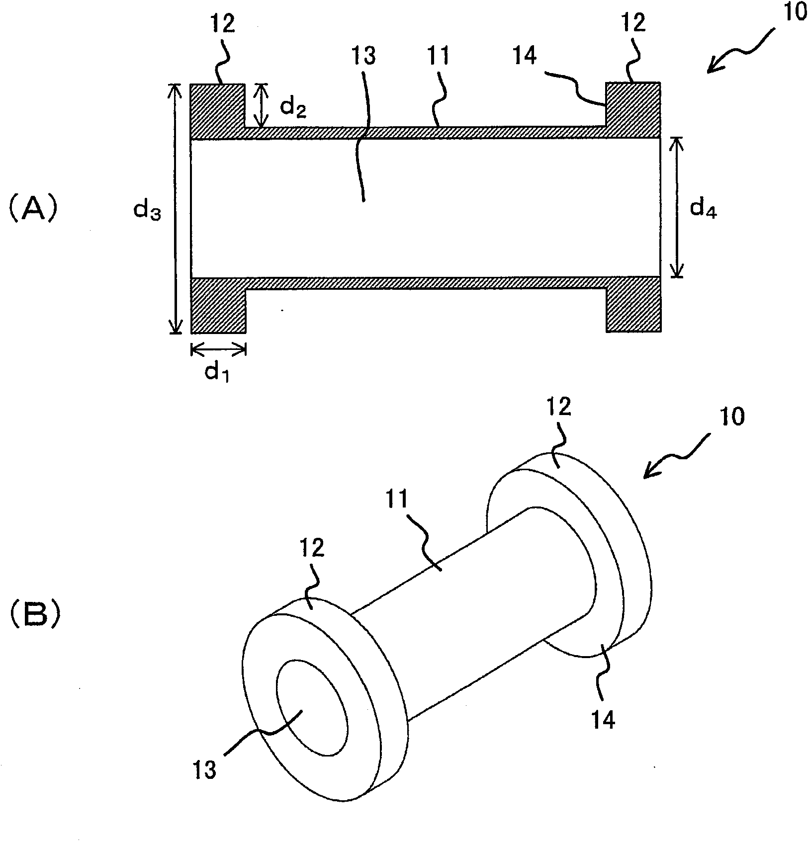
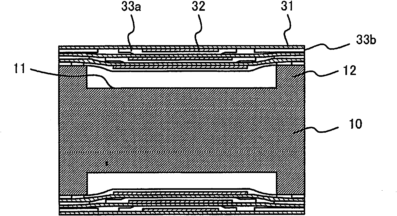
[0066] Such as figure 1 As shown, the winding core 10 of this embodiment is a dumbbell-shaped winding core in which a small-diameter relaxation portion 11 and a large-diameter support portion 12 are formed on the winding surface side of the wafer processing tape. The relaxation portion 11 is provided at a position corresponding to the tape for wafer processing (constituted by the adhesive layer and the label portion of the adhesive film covering the adhesive layer), and the supporting portion 12 supports the peripheral portion 33b of the adhesive film on the outside of the relaxation portion 11. way to form. In addition, a cylindrical hollow portion 13 is formed at the rotation center of the winding core.

[0067] The material of the winding core is not particularly limited, and ABS resin, vinyl chloride resin, iron, and the like can be selected from the viewpoint of ease of handling, weight, and the like.

[0068] (Easy Department 11)

[0069] Such as figure 1 As shown,...

no. 2 approach

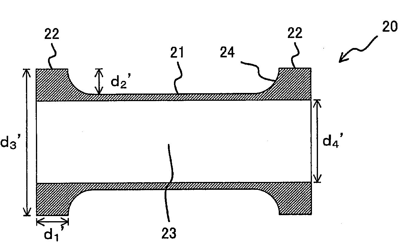
[0076] The winding core 20 of the second embodiment is a winding core in which the relaxation portion side portion 14 of the winding core 10 of the first embodiment is formed into a curved surface. image 3 A cross-sectional view of the winding core 20 of the second embodiment is shown. The winding core 20 is a deformed dumbbell-shaped winding core in which a relaxation portion 21 with a small diameter and a support portion 22 with a large diameter are formed on the winding surface side of the wafer processing tape. Such as image 3 As shown, the relaxation portion 21 is formed by the relaxation portion 21 , which is a cylindrical surface with a smaller diameter than the support portion 22 with respect to the rotation center axis of the winding core 20 , and the relaxation portion side 24 , which is a curved surface continuously curved from the relaxation portion 21 .

[0077]The relaxation portion 21 is provided at a position corresponding to the adhesive layer of the dicing...

Embodiment 1

[0092] Make the diameter of the supporting part (d 3 ) is set to 148mm, the width of the support part (d 1 ) is set to 30mm, and the depth of the relaxation part from the surface of the support part to the surface of the relaxation part (d 2 ) is set to 1.0mm, the diameter of the cavity (d 4 ) was set to 76.2 mm, and the length of the core in the longitudinal direction was set to 290 mm. Furthermore, a dumbbell-shaped core in which the center of the support portion, the relaxation portion, and the hollow portion coincided with the core rotation center was used as Example 1.


PUM

PropertyMeasurementUnit
diameteraaaaaaaaaa
diameteraaaaaaaaaa
diameteraaaaaaaaaa

Abstract

The invention provides a winding core capable of winding a wafer-processing belt into the shape of a scroll, wherein the wafer-processing belt comprises a demoulding membrane provided with an adhesive layer and an adhesive film, and is capable of sufficiently preventing imprints form being formed on the adhesive layer. The wafer-processing belt comprises the demoulding membrane, the adhesive layer which is arranged on the surface of the demoulding membrane and has a required plane shape and the adhesive film which is provided with a label part and a peripheral part, wherein the label part covers the adhesive layer, is arranged to be contacted with the demoulding membrane at the periphery of the adhesive layer, and has the required plane shape; and the peripheral part is arranged to enclose the exterior of the label part. The winding core comprises an alleviating part and a supporting part, wherein moderate winding pressure is generated by the alleviating part at least at a position corresponding to the adhesive layer, and the supporting part is formed outside the alleviating part in the width direction of the wound wafer-processing belt and used for supporting the wafer-processing belt.

Description

technical field [0001] The present invention relates to a winding core for winding a wafer processing tape into a reel shape, and more particularly to a winding core for winding a wafer processing tape having a dicing die bonding film into a reel shape. The soldering film has two functions of dicing tape and die bonding film. Background technique [0002] In recent years, there has been developed a dicing die-bonding film that serves both as a dicing tape for fixing a semiconductor wafer when dicing the semiconductor wafer into individual chips and for bonding the diced semiconductor chip to a lead frame. And packaging substrates, etc. or used for stacking and bonding die-bonding films between semiconductor chips (also called die-attach films) in package-on-package. [0003] Such a dicing / die-bonding film may be subjected to pre-cut processing in consideration of workability such as attaching to a wafer and attaching to a ring frame during dicing. [0004] Examples of pre-...

Claims


Application Information

Patent Timeline
Patent Type & Authority Applications(China)
IPC IPC(8): H01L21/68C09J163/04
Inventor 木村和宽丸山弘光中村俊光
Owner FURUKAWA ELECTRIC CO LTD
Why Eureka
Try Eureka